Valve plate rod straightening device

A straightening device and valve disc technology, applied in the field of valve production devices, can solve the problems of waste of financial resources and high rework rate, and achieve the effect of ensuring the straightening effect

Inactive Publication Date: 2020-04-14
扬州光辉汽车零部件有限公司
View PDF0 Cites 0 Cited by
  • Summary
  • Abstract
  • Description
  • Claims
  • Application Information

AI Technical Summary

Problems solved by technology

However, our company adopts the second method. The straightening process is indeed significantly improved, but the rework rate is very high, so it causes a lot of waste of manpower, material resources and financial resources.

Method used


Image

  • Valve plate rod straightening device
  • Valve plate rod straightening device

Examples


Embodiment Construction

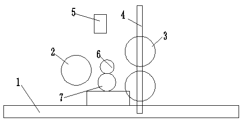
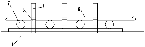
[0015] A valve disc rod straightening device, the straightening device includes a workbench 1, a roller 2 is arranged on one side of the workbench 1, and a roller 2 3 is arranged on the other side of the workbench 1;

[0016] The first roller 2 and the second roller 3 perform rotational movement, the first roller 2 is fixed in the horizontal direction and is arranged in one group, and the second roller 3 is two groups and can move horizontally;

[0017] Two groups of rollers 3 are arranged up and down, and the position of said roller one 2 in the longitudinal direction is in the middle of the longitudinal position of two groups of rollers 3 .

[0018] The two groups of rollers 3 are connected to the elevating rod 4 by a lifting device, and a controller is provided to control the two groups of rollers 3 to realize synchronous movement on the elevating rod 4, and the two groups of rollers 3 move in opposite directions on the elevating rod 4 .

[0019] A lubricating oil spraying...


PUM


Abstract

The invention relates to a valve plate rod straightening device. The straightening device comprises a workbench (1). A first roller (2) is arranged on one side of the workbench (1), and second rollers(3) are arranged on the other side of the workbench (1). The first roller (2) and the second rollers (3) do rotating motion. One set of the first roller (2) is fixed in the horizontal direction. Thetwo sets of second rollers (3) are arranged and can move in the horizontal direction. The two sets of second rollers (3) are arranged up and down. The position of the first roller (2) in the longitudinal direction is in the middle of the longitudinal position of the two sets of second rollers (3). According to the valve plate rod straightening device, the first roller and the second rollers are ingeniously arranged, so that the straightening device can form the good support and straightening effect on a valve, the upper and lower symmetry of the second rollers can effectively keep the valve stable in the operation process, and the straightening effect of the valve is guaranteed.

Description

technical field [0001] The invention relates to a valve disc rod straightening device, which belongs to the technical field of valve production devices. Background technique [0002] At present, domestic large and small valve factories adopt two methods: the first is the manual straightening method, that is, use a special bracket to support the rod of the valve to balance it, and measure the jump of the rod with a dial indicator. Hit it hard with a hammer to make it anti-deformed; the second method is the straightening method of the thread rolling machine, that is, buy a thread rolling machine and modify the thread rolling disc to straighten the valve stem. And our company adopts the second method. The straightening process is indeed significantly improved, but the rework rate is very high, so it causes a lot of waste of manpower, material resources and financial resources. Contents of the invention [0003] The purpose of the present invention is to provide a valve disc ...

Claims


Application Information

Patent Timeline
Patent Type & Authority Applications(China)
IPC IPC(8): B21D3/02
CPCB21D3/02
Inventor 杜举才杜学坤徐巍巍李康壮
Owner 扬州光辉汽车零部件有限公司
Why Eureka
Try Eureka