
Clamping mechanical arm for 3D printer nozzle

A 3D printer and robotic arm technology, applied in the field of 3D printing, can solve the problems of inconvenient disassembly and installation, damage to the nozzle, inconvenient adjustment of the mechanical length and printing bin, and achieve the effect of preventing damage and preventing angle changes.

Inactive Publication Date: 2020-04-14
芜湖英罗智能制造有限公司
View PDF7 Cites 2 Cited by
  • Summary
  • Abstract
  • Description
  • Claims
  • Application Information

AI Technical Summary

Problems solved by technology

[0006] The purpose of the present invention is to provide a clamping mechanical arm for the nozzle of a 3D printer, to solve the influence of the twisting force in the operation of the servo motor in the prior art proposed in the above-mentioned background technology, it is inconvenient to disassemble and install and damage the nozzle when clamping, and the mechanical arm The length and the printing chamber are inconvenient to adjust, etc.

Method used


Image

  • Clamping mechanical arm for 3D printer nozzle
  • Clamping mechanical arm for 3D printer nozzle
  • Clamping mechanical arm for 3D printer nozzle

Examples


Embodiment Construction

[0027] The following will clearly and completely describe the technical solutions in the embodiments of the present invention with reference to the accompanying drawings in the embodiments of the present invention. Obviously, the described embodiments are only some, not all, embodiments of the present invention. The specific embodiments described here are only used to explain the present invention, not to limit the present invention. Based on the embodiments of the present invention, all other embodiments obtained by persons of ordinary skill in the art without making creative efforts belong to the protection scope of the present invention.

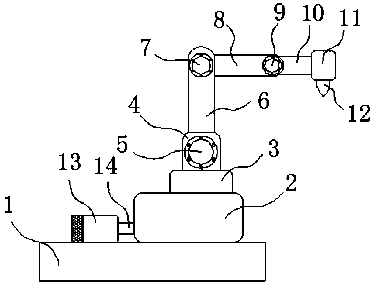
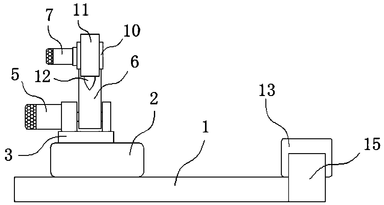
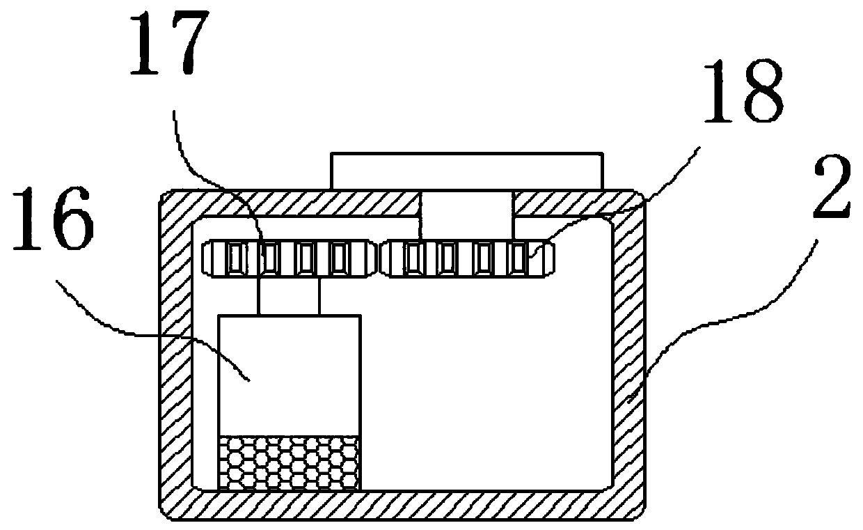
[0028] The present invention provides such Figure 1-6 A clamping mechanical arm for a nozzle of a 3D printer shown, including a printer body 1;

[0029] according to figure 1 with figure 2 , in order to realize the rotation of the mechanical arm, a rotary box 2 is movably installed on the upper surface of the printer body 1, and a fo...


PUM


Abstract

The invention discloses a clamping mechanical arm for a 3D printer nozzle, which comprises a printer body. The printer body is connected with a mechanical arm structure through a rotating box. The topend of the mechanical arm structure is connected with a clamp. Clamping plates are connected to the two sides of the front end of the clamp. The inner sides of the two groups of clamping plates are connected with silica gel plates. A nozzle is clamped between the silica gel plates. A fifth stepping motor and a connecting shaft box are installed at one end of the printer body, the fifth stepping motor is in engaged connection with a second bevel gear through a first bevel gear, the second bevel gear is connected to a screw rod, a first sliding block is arranged at the bottom of the rotating box, and the first sliding block is in threaded connection to the screw rod. The mechanical arm is adopted for fixing and clamping the nozzle, the printing process is achieved, the motor is arranged formoving and adjusting the mechanical arm system, the mechanical arm can conduct all-around printing operation, the adjusting clamp is arranged, the silica gel plate and the spring are arranged on theclamp, and the nozzle is prevented from being damaged by clamping.

Description

technical field [0001] The invention belongs to the technical field of 3D printing, and in particular relates to a clamping mechanical arm for a nozzle of a 3D printer. Background technique [0002] 3D printing is a kind of rapid prototyping technology, also known as additive manufacturing. It is a technology based on digital model files and using bondable materials such as powdered metal or plastic to construct objects by layer-by-layer printing. . [0003] 3D printing is usually achieved using digital technology material printers. It is often used to make models in the fields of mold manufacturing and industrial design, and is gradually used in the direct manufacture of some products. There are already parts printed using this technology. The technology has applications in jewelry, footwear, industrial design, architecture, engineering and construction, automotive, aerospace, dental and medical industries, education, geographic information systems, civil engineering, fir...

Claims


Application Information

Patent Timeline
Patent Type & Authority Applications(China)
IPC IPC(8): B25J9/10B25J9/12B25J9/16B25J11/00B33Y30/00
CPCB25J9/102B25J9/12B25J9/1682B25J11/00B33Y30/00
Inventor 刘继舟
Owner 芜湖英罗智能制造有限公司
Learn More