

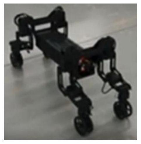
A parallel wheel-foot robot leg structure and mobile robot
A robot and wheel foot technology, which is applied in the field of robots, can solve the problems of small weight and large joint swing angle, and achieve the effect of large rotation angle, reduced moment of inertia, and increased stiffness
- Summary
- Abstract
- Description
- Claims
- Application Information
AI Technical Summary
Problems solved by technology
Method used
Image

Examples
Embodiment 1
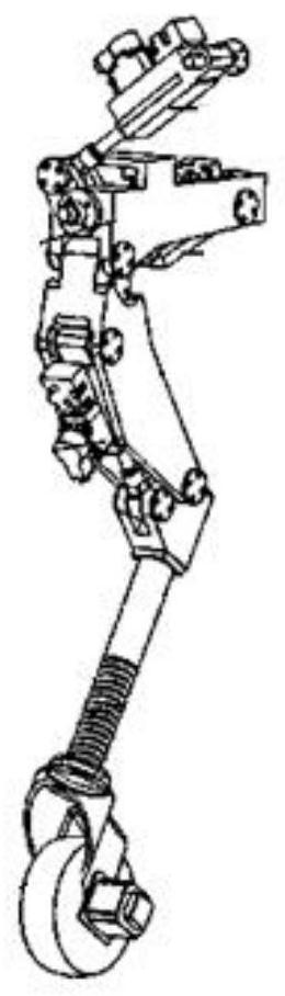
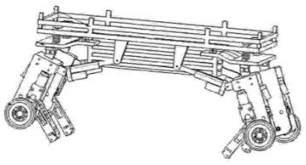
[0053] Embodiment 1: see attached Figure 9a-15 As shown, the parallel wheel-footed robot leg structure of the present invention includes a frame, a side swing axis module, a front swing axis module, a thigh module, a shank module and rollers. The leg structure is a parallel mechanism, in which the frame is a static platform, and the lower leg is a dynamic platform at the end. The side swing can be a roll motion (Roll), and the front swing can be a pitch motion (Pitch).
[0054] More specifically, the drive module 1 includes a frame 104 and three drive motors 101, 102, 103 fixedly connected to the frame 104, the output axes of the three drive motors 101, 102, 103 are parallel; the side swing axis module 2 includes The side swing shaft 211 arranged on the frame 104 along the axial direction perpendicular to the drive motor output shaft; the connecting block 501 is fixed on the side swing shaft 211, which can drive the calf module 3, thigh module 4, and front swing through the ...
Embodiment 2
[0072] Embodiment 2: as Figure 17-21 , the difference between this embodiment and Embodiment 1 is that a sector gear 308 is also fixed on the outer side of the flange 105 of the front swing reducer of the thigh, and the passive parallel shaft gear 302 is an incomplete passive parallel shaft gear 302, which refers to a part of the outer circumference There are no tooth settings on the face. When changing from a footed movement to a wheeled movement, first make the side swing angle zero, the big and small legs start to turn upwards from the upright posture, the forward swing speed of the thigh is equal to the forward swing speed of the calf, and the sector gear 308 and the passive parallel shaft gear 302 Gradually meshing, because the passive parallel shaft gear 302 is an incomplete gear, and the active parallel shaft gear 301 and the passive parallel shaft gear 302 are gradually disengaged. The ground continues to rotate with the active parallel shaft gear 301, and the robot ...
Embodiment 3
[0073] Embodiment 3: The difference between this embodiment and Embodiment 1 is: the side swing driving gear 201, the calf swing forward driving gear 202, the thigh swing forward driving gear 203, the thigh swing forward passive gear 204, the calf swing forward driven gear 207, the thigh The forward swing transition gear 206, the forward swing transition gear 209 of the shank and the side swing driven gear 210 are all bevel gears.
PUM
 Abstract
Description
Claims
Application Information