
Rapid positioning device for machining

A positioning device and machining technology, applied in the direction of metal processing equipment, metal processing machinery parts, manufacturing tools, etc., can solve the problems of low production efficiency and achieve the effect of improving precision

Inactive Publication Date: 2020-04-17
SICHUAN VOCATIONAL & TECHN COLLEGE
View PDF14 Cites 1 Cited by
  • Summary
  • Abstract
  • Description
  • Claims
  • Application Information

AI Technical Summary

Problems solved by technology

Common thin workpieces are mostly processed by mirror surface processing. Mirror surface processing is mainly surface processing without removing material. During mirror surface processing, the workpiece is ground by a grinder installed on a milling machine. However, due to inconsistent positioning heights, it is necessary to Multiple surfaces of the workpiece are tool-set to prevent the tool from colliding with the tool during processing. In order to improve the processing efficiency, most of the existing workpieces are ground by sandblasting during processing, but the workpiece still needs to be ground after grinding. Placed on the workbench to perform operations such as drilling and slotting on the workpiece, resulting in low production efficiency

Method used


Image

  • Rapid positioning device for machining
  • Rapid positioning device for machining
  • Rapid positioning device for machining

Examples


Embodiment

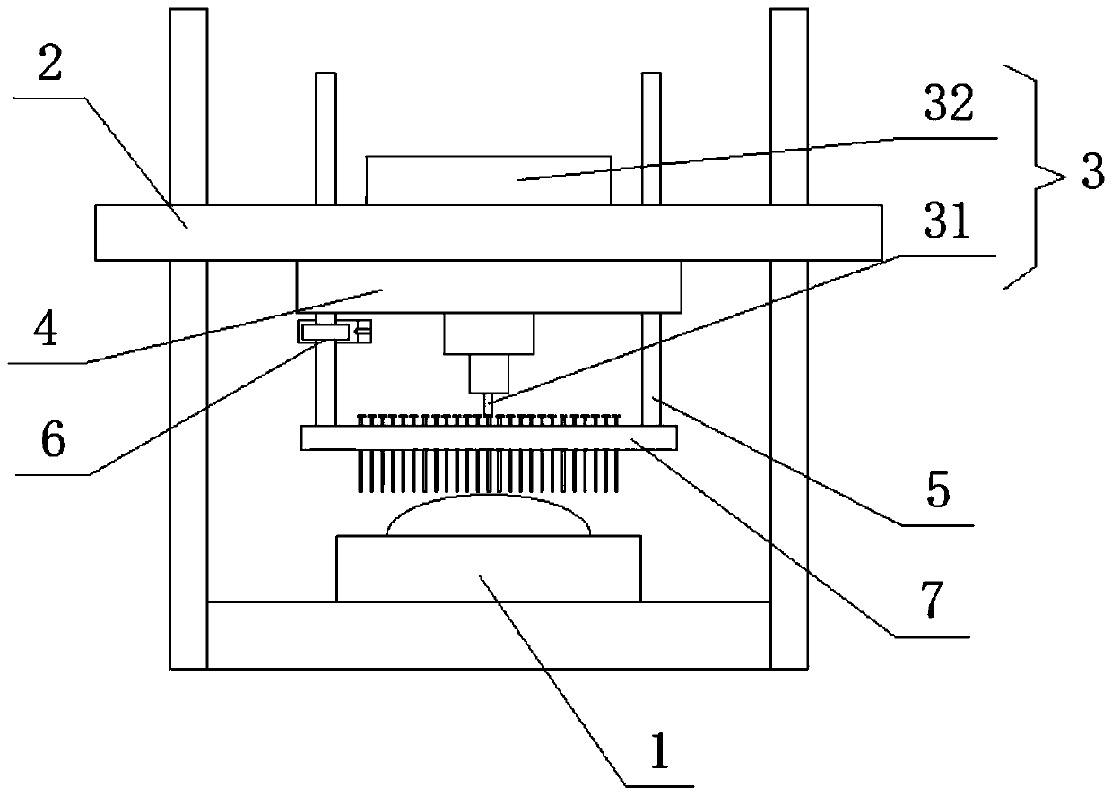
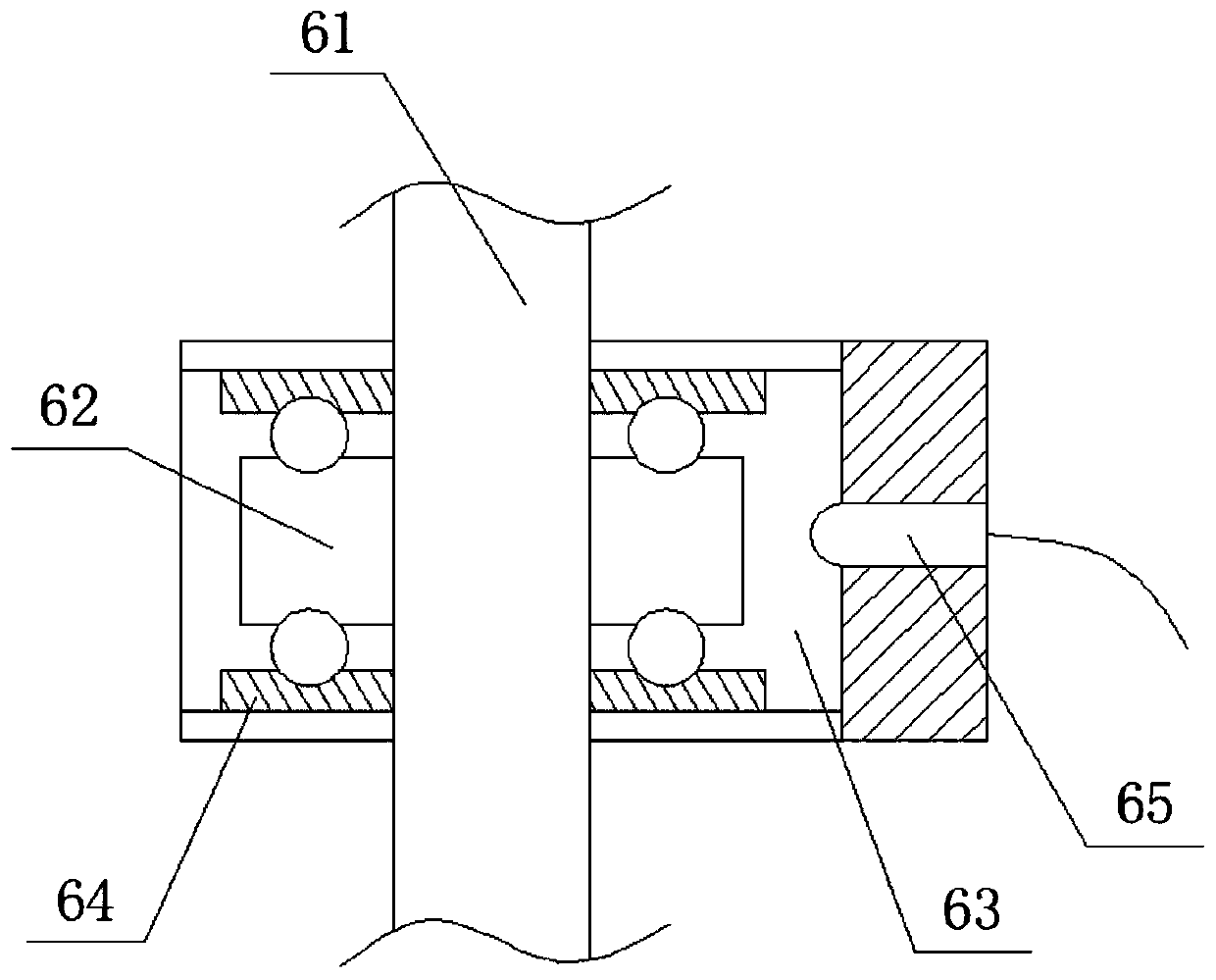
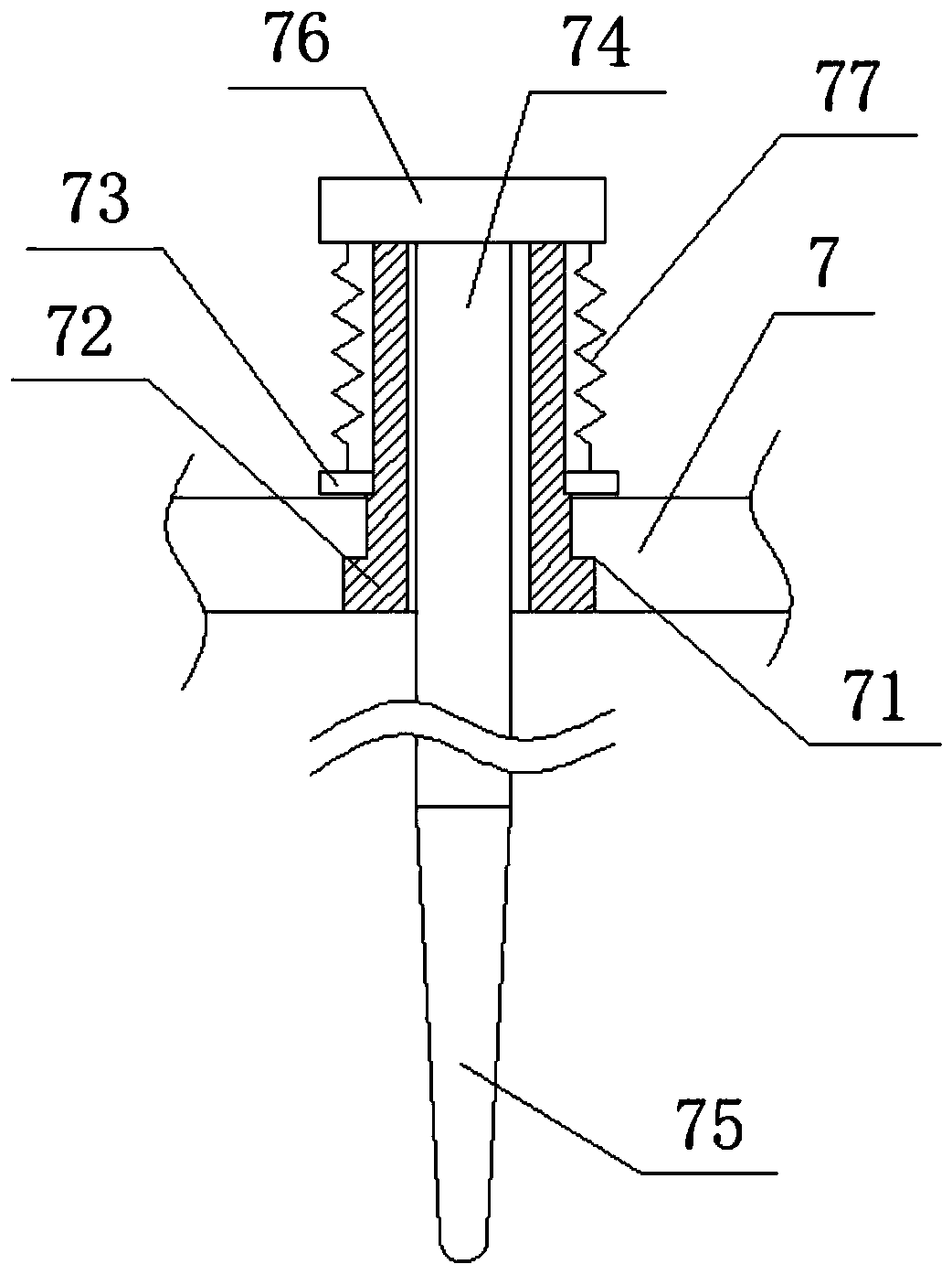
[0021] Such as Figure 1 ~ Figure 4 As shown, the rapid positioning device for machining provided in this embodiment includes a clamping table 1, a support frame 2 and a cutting system 3. The four corners of the clamping table 1 are equipped with a support frame 2, and the support frame 2 is suspended and installed with a The cutting system 3 matched with the clamping table 1, the cutting system 3 is composed of a tool 31 and a control system 32 for controlling the movement of the tool 31, an auxiliary positioning system is also provided between the cutting system 3 and the clamping table 1, the The auxiliary positioning system includes a support 4, a linear movement pair 5, a ball screw 6, a probe board 7 and a measuring system 8. The support 4 is detachably installed on the support frame 2 on one side of the cutting system 3, and the support 4 is provided with There are at least three vertically arranged linear moving pairs 5, wherein one of the linear moving pairs 5 is also...


PUM


Abstract

The invention discloses a rapid positioning device for machining. The device comprises a clamping table, supporting frames and a cutting system. Supporting frames are installed at the four corners ofthe clamping table. The cutting system matched with the clamping table is mounted on the supporting frames in a hanging manner; the cutting system consists of a cutter and a control system for controlling the movement of the cutter; an auxiliary positioning system is further arranged between the cutting system and the clamping table; the auxiliary positioning system comprises a support, linear moving pairs, a ball screw, a probe plate and a measuring system; the support is installed on the supporting frame; the support is connected with the probe plate located below the support through at least three vertically-arranged linear moving pairs; the probe plate is provided with a plurality of distance measuring probes; and the bottom ends of the distance measuring probes are all arranged in thesame horizontal plane. The distance between the cutter and the workpiece is measured by arranging the probe plate and the ball screw, and meanwhile, the outline of the surface of the workpiece is detected by the probe plate, so that the cutter is quickly set for the workpiece.

Description

technical field [0001] The invention relates to the field of machining equipment, in particular to a quick positioning device for machining. Background technique [0002] In mechanical processing, tool setting becomes one of the most important links when processing thin and special-shaped workpieces. However, due to the inconsistent height of the top surface of the special-shaped workpieces, there are many points that need to be set. Tool setting is to confirm The location where the workpiece is processed. Common thin workpieces are mostly processed by mirror surface processing. Mirror surface processing is mainly surface processing without removing material. During mirror surface processing, the workpiece is ground by a grinder installed on a milling machine. However, due to inconsistent positioning heights, it is necessary to Multiple surfaces of the workpiece are tool-set to prevent the tool from colliding with the tool during processing. In order to improve the processi...

Claims


Application Information

Patent Timeline
Patent Type & Authority Applications(China)
IPC IPC(8): B23Q17/20B23Q17/22
CPCB23Q17/20B23Q17/22B23Q17/2233B23Q17/2241
Inventor 许江蒋轲冯大强蔡自强杨舒淇
Owner SICHUAN VOCATIONAL & TECHN COLLEGE
Learn More