
Flying knife setting device for disc chipper

A disc-type chipper and knife setting device technology, which is applied in the manufacture of veneer, wood processing equipment, manufacturing tools, etc., can solve the problem of exceeding the specified length and thickness of wood chips, inconsistent installation width B, high failure rate of wood chips, etc. problem, to achieve the effect of convenient processing, convenient tool setting and simple structure

Active Publication Date: 2015-12-30
江苏保龙机电制造有限公司
View PDF7 Cites 0 Cited by
  • Summary
  • Abstract
  • Description
  • Claims
  • Application Information

AI Technical Summary

Problems solved by technology

[0004] (1) Measurement errors are prone to occur during repeated replacement of flying knives
[0005] (2) The installation width B of the 8 flying knives is inconsistent with each other, resulting in the length and thickness of the wood chips exceeding the regulations, resulting in an excessive failure rate of wood chips

Method used


Image

  • Flying knife setting device for disc chipper
  • Flying knife setting device for disc chipper
  • Flying knife setting device for disc chipper

Examples


Embodiment

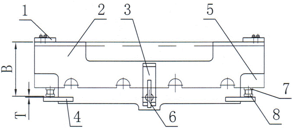
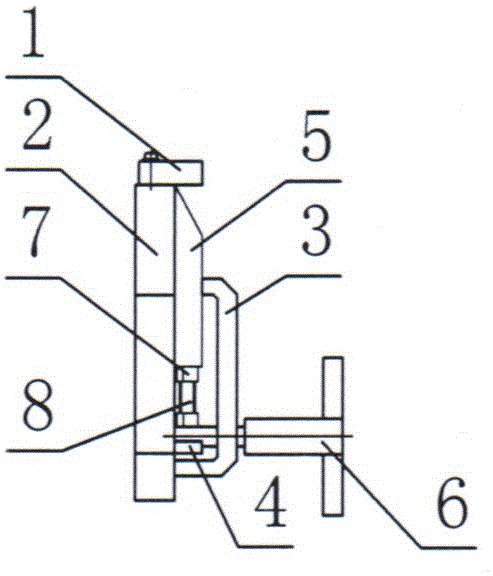
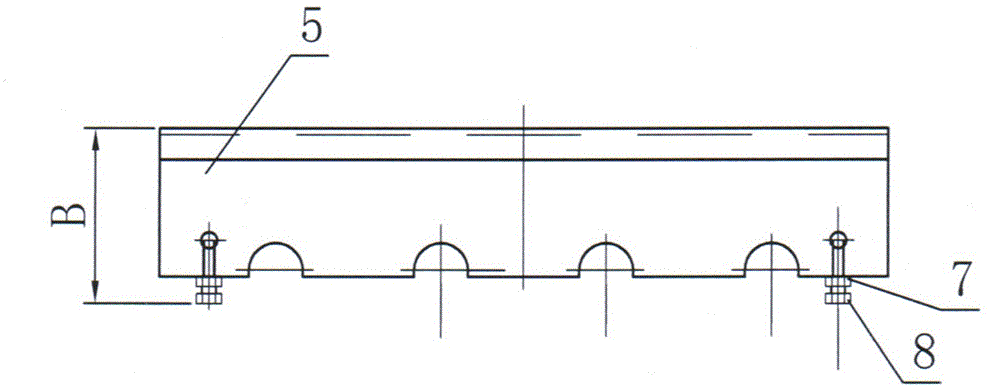
[0021] Such as Figure 1~3 As shown, a flying knife setting device for a disc chipper includes a base plate 2, a first positioning block 1 fixed on the upper side of the base plate 2, a second positioning block 4 fixed on the lower side of the base plate 2, and a A flying knife 5 between a positioning block 1 and a second positioning block 4, a knife pressing block 3 and a rotary handle 6, wherein:

[0022] ——The rotating handle 6 passes through the press block 3 and connects with the bottom plate 2, and the flying knife 5 is located between the press block 3 and the bottom plate 2;

[0023] ——The flying knife 5 is also provided with a locking nut 7 and an adjusting bolt 8. The locking nut 7 is sleeved on the adjusting bolt 8. The two adjusting bolts 8 are located on the lower side of the flying knife 5. The adjusting bolt 8 and the second positioning block 4 separation.

[0024] When dismounting, the rotating handle 6 is released, and the knife pressing block 3 will leave t...


PUM


Abstract

The invention relates to a disc chipper, in particular to a disc chipper fly cutter setting device. The disc chipper fly cutter setting device comprises a bottom plate (2), first positioning blocks (1) fixedly connected to the upper side of the bottom plate (2), second positioning blocks (4) fixedly connected to the lower side of the bottom plate (2), and a fly cutter (5) located between the first positioning blocks (1) and the second positioning blocks (4) and further comprises a cutter pressing block (3) and a rotating handle (6). The rotating handle (6) penetrates through the cutter pressing block (3) and is connected with the bottom plate (2), the fly cutter (5) is located between the cutter pressing block (3) and the bottom plate (2), the fly cutter (5) further comprises locking nuts (7) and adjusting bolts (8), and the adjusting bolts (8) are separated from the second positioning blocks (4). Due to the adoption of the technical scheme, the disc chipper fly cutter setting device is high in accuracy and simple in structure.

Description

technical field [0001] The invention relates to a disc chipper, in particular to a flying knife setting device for the disc chipper. The invention belongs to the technical field of mechanical equipment manufacturing and processing. Background technique [0002] The chipper is one of the key equipment in the wood-based panel and paper-making production line. Its working principle is: the high-speed rotary cutter head drives the flying knife, and under the action of the flying knife and the bottom knife, the garden wood is cut into flakes to meet the requirements of wood-based panel and papermaking. Require. Although the flying knife is made of special materials and has been quenched, in wood chipping, the tip of the flying knife will produce curling and jumping edges after 2 to 4 hours of operation. At this time, the flying knife needs to be sharpened, otherwise the chipping effect will be affected. It is more troublesome to reinstall the knife setting after the flying kni...

Claims


Application Information

Patent Timeline
Patent Type & Authority Patents(China)
IPC IPC(8): B27L5/06
Inventor 周水保周伟李树安圣爱兵
Owner 江苏保龙机电制造有限公司
Learn More