
A 3D printer model cooling system

A 3D printer and cooling system technology, applied to 3D object support structures, coating devices, manufacturing tools, etc., can solve problems such as uncontrollable temperature, high internal temperature, and inability to print, so as to achieve good cooling effect and improve printing quality , prevent softening effect

Active Publication Date: 2021-09-07
河南速维电子科技有限公司
View PDF0 Cites 0 Cited by
  • Summary
  • Abstract
  • Description
  • Claims
  • Application Information

AI Technical Summary

Problems solved by technology

[0002] Most of the 3D printers currently on the market have a simple model cooling system structure, just a fan, which can only blow a single piece of wind. In fact, the air near the printer head is blown to the model through the fan, which belongs to internal circulation, and the temperature is uncontrollable.
The result is that only ordinary materials such as traditional PLA and ABS can be printed. For materials with high printing temperature such as PETG and PC, the cooling fan will blow out air due to the high internal temperature of the printer box 2 (generally between 50°C and 150°C). too hot, the effect is not obvious
For PEEK, an ultra-high temperature (400-500°C) semi-crystalline material that requires secondary annealing, it cannot be printed

Method used


Image

  • A 3D printer model cooling system
  • A 3D printer model cooling system
  • A 3D printer model cooling system

Examples


Embodiment Construction

[0024] In order to make the purpose, technical solution and advantages of the present invention clearer, the technical solution of the present invention will be described in detail below. Apparently, the described embodiments are only some of the embodiments of the present invention, but not all of them. Based on the embodiments of the present invention, all other implementations obtained by persons of ordinary skill in the art without making creative efforts fall within the protection scope of the present invention.

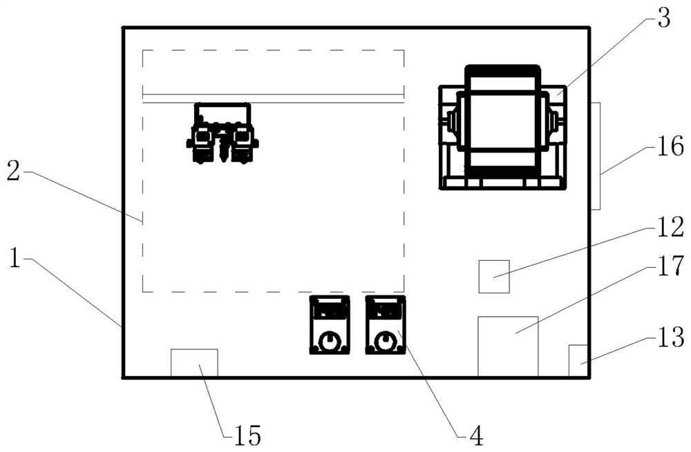
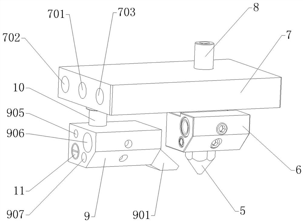
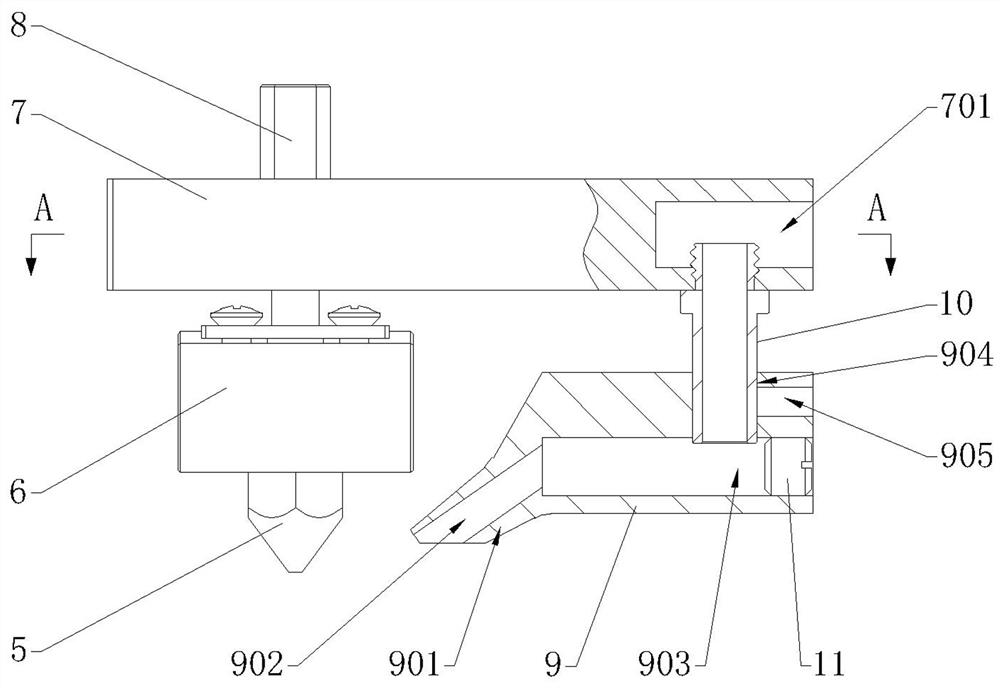
[0025] see Figure 1-Figure 7 As shown, the present invention provides a 3D printer model cooling system, including a nozzle assembly and a fan 3, the nozzle assembly includes a nozzle 5, a wire feeding throat 8 connected to the nozzle 5, and a nozzle heating block arranged on the nozzle 5 6. The wire feeding throat 8 is provided with a mounting plate 7, and the end of the mounting plate 7 away from the wire feeding throat 8 is provided with an air inlet 701; o...


PUM


Abstract

The invention discloses a 3D printer model cooling system, which includes a nozzle assembly and a fan. The nozzle assembly includes a nozzle, a wire feeding throat and a nozzle heating block; a mounting plate is arranged on the wire feeding throat, and an air inlet is arranged on the mounting plate An air heating block is arranged on one side of the nozzle, and an air duct is arranged inside the air heating block, and one end of the air duct is blocked by a plug; an air nozzle is arranged at one end of the air heating block, and an air outlet connected to the air duct is arranged in the air nozzle; The air heating block is fixed to the mounting plate through the air intake throat, which connects the air intake hole with the air duct; the air heating block is also equipped with a heating device and a temperature sensor; the heating device and the temperature sensor are connected to the thermostat Sexual connection; the fan is arranged outside the box of the 3D printer, and the outlet end of the fan is connected to the air inlet through a pipe. The invention can improve the cooling effect of the model, improve the quality of printing, control the temperature of the air flow blown out, and is suitable for printing various types of consumables.

Description

technical field [0001] The invention relates to the technical field of 3D printers, in particular to a cooling system for a 3D printer model. Background technique [0002] Most of the 3D printers currently on the market have a simple model cooling system, just a fan, which can only blow a single piece of air. In fact, the air near the printer head is blown to the model through the fan, which belongs to internal circulation, and the temperature is uncontrollable. The result is that only ordinary materials such as traditional PLA and ABS can be printed. For materials with high printing temperature such as PETG and PC, the cooling fan will blow out air due to the high internal temperature of the printer box 2 (generally between 50°C and 150°C). Too hot to be effective. For PEEK, an ultra-high temperature (400-500°C) semi-crystalline material that requires secondary annealing, it cannot be printed. Contents of the invention [0003] In order to solve the deficiencies of the ...

Claims


Application Information

Patent Timeline
Patent Type & Authority Patents(China)
IPC IPC(8): B29C64/209B29C64/295B29C64/393B29C64/30B29C64/379B29C35/16B33Y30/00B33Y50/02B33Y40/00B33Y40/20B29K71/00
CPCB29C35/16B29C2035/1616B29C2035/1658B29K2071/00B33Y30/00B33Y40/00B33Y50/02B29C64/209B29C64/295B29C64/30B29C64/379B29C64/393
Inventor 樊立业陈宝华王亚丽张昕博
Owner 河南速维电子科技有限公司
Learn More