
Light-sensation-control-based electricity-saving device capable of quantitatively cleaning sewage tank

A power-saving device and sewage tank technology, which is applied in the direction of light water/sewage treatment, water/sewage treatment, water/sewage multi-stage treatment, etc., can solve the increase in user input costs, waste of electricity in sewage treatment tanks, and increased use Issues such as the cost of the operator, to achieve the effects of saving power consumption, improving durability, and saving costs

Inactive Publication Date: 2020-04-17
卢章山
View PDF0 Cites 8 Cited by
  • Summary
  • Abstract
  • Description
  • Claims
  • Application Information

AI Technical Summary

Problems solved by technology

[0006] Aiming at the deficiencies of the prior art, the present invention provides a power-saving device based on light-sensing control that can quantitatively clean sewage tanks, which has the advantages of saving electricity and improving the durability of equipment, and solves the problem of sewage treatment in previous sewage treatment tanks. During treatment, regardless of whether there is sewage to be treated or the amount of sewage, the sewage treatment tank will always be in operation, which will cause a large amount of waste of electricity in the sewage treatment tank, increase the cost of the user, and when there is no sewage treatment Or when the amount of sewage is small, the parts inside the sewage treatment tank will always be in operation, which is very likely to cause excessive consumption of parts inside the tank, affecting the service life of the sewage treatment tank, which will cause sewage The processing is not timely, and it will also increase the user's input cost

Method used


Image

  • Light-sensation-control-based electricity-saving device capable of quantitatively cleaning sewage tank
  • Light-sensation-control-based electricity-saving device capable of quantitatively cleaning sewage tank
  • Light-sensation-control-based electricity-saving device capable of quantitatively cleaning sewage tank

Examples


Embodiment Construction

[0027] The following will clearly and completely describe the technical solutions in the embodiments of the present invention with reference to the accompanying drawings in the embodiments of the present invention. Obviously, the described embodiments are only some, not all, embodiments of the present invention. Based on the embodiments of the present invention, all other embodiments obtained by persons of ordinary skill in the art without making creative efforts belong to the protection scope of the present invention.

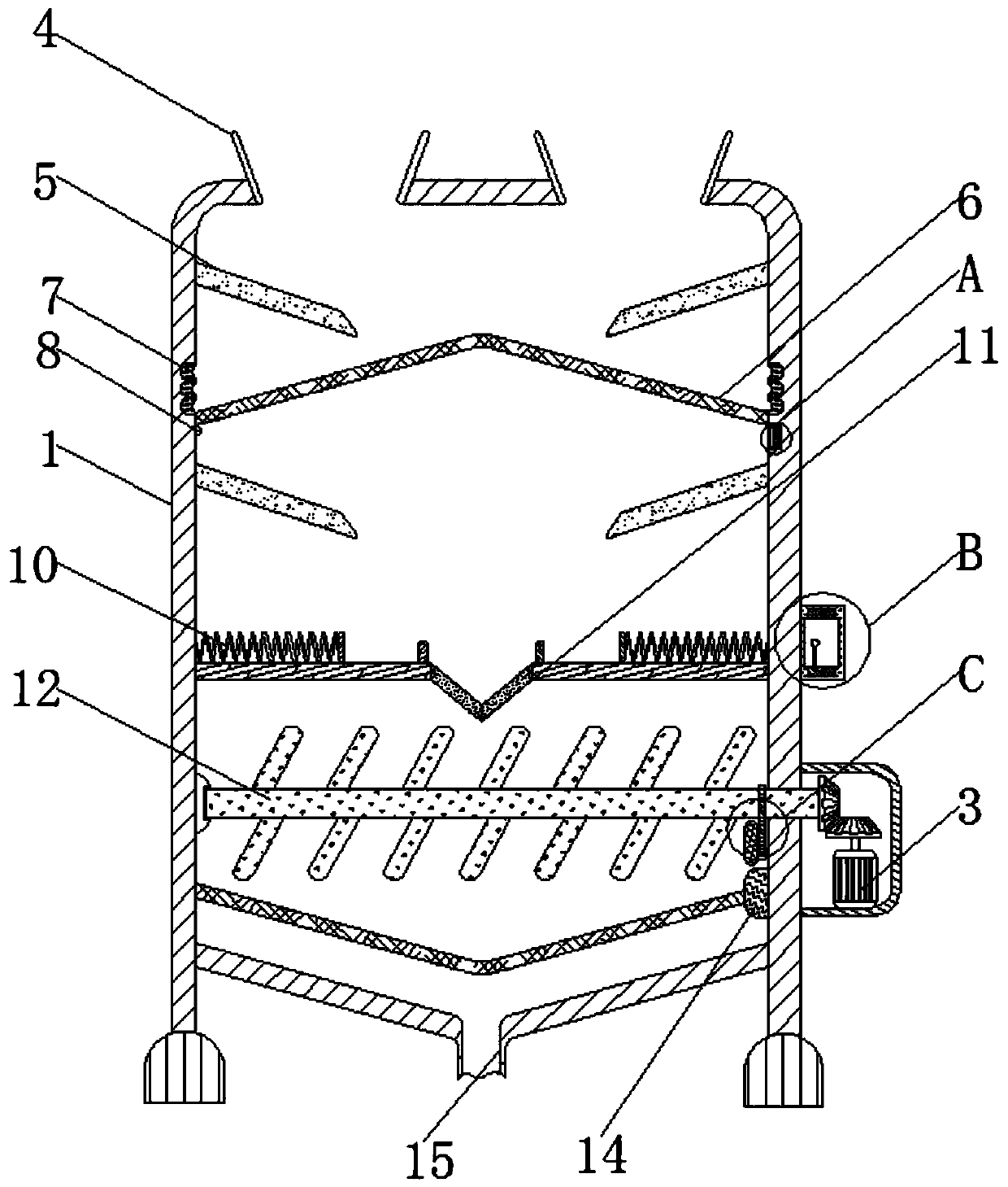
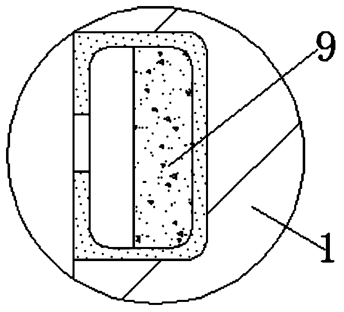
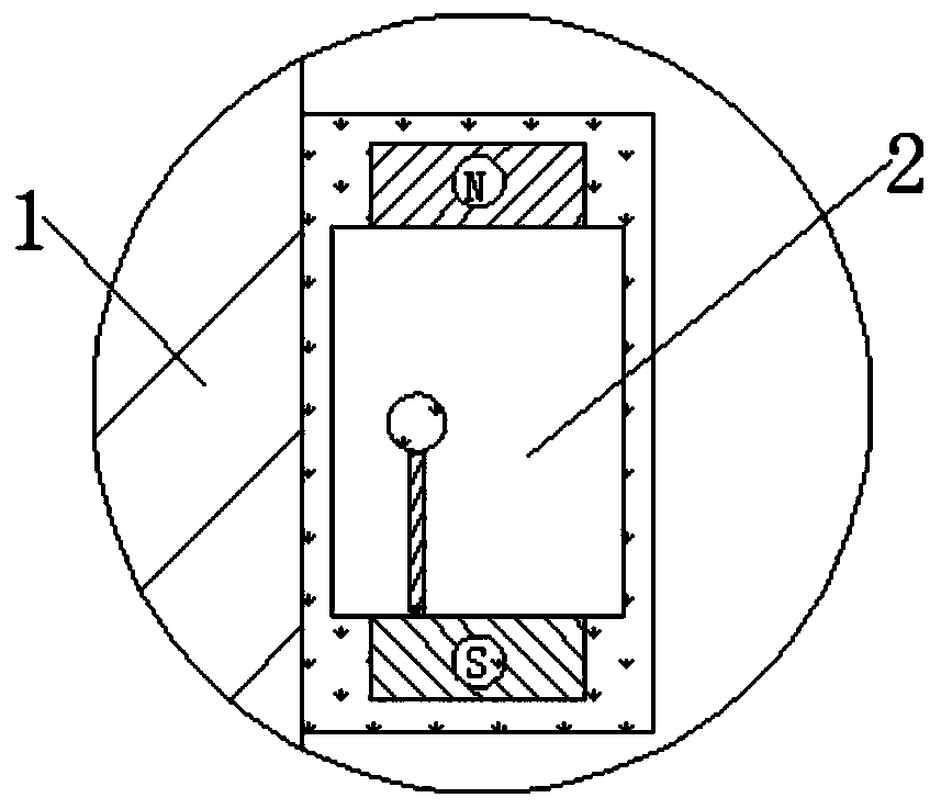
[0028] see Figure 1-5 , an energy-saving device for quantitatively cleaning sewage tanks based on light sensing control, including a housing one 1, the outside of the housing one 1 is fixedly connected with a sensor 2, and the sensor 2 is mainly composed of a housing two, a positive pole, a negative pole, a support rod, Composed of copper rods, the positive and negative electrodes are fixedly connected inside the second shell, the support rod is movably conne...


PUM


Abstract

The invention relates to the technical field of sewage treatment equipment, and discloses a light-sensation-control-based electricity-saving device capable of quantitatively cleaning a sewage tank. The device comprises a first shell, wherein a sensor is fixedly connected to the outer portion of the first shell, the exterior of the first shell is movably connected with a driving structure, a waterinlet is fixedly connected to the top of the first shell, a flow guide plate is fixedly connected to the interior of the first shell, a filter plate is fixedly connected to the interior of the first shell, a suction pipe is fixedly connected to the interior of the first shell, a direct illuminating lamp is fixedly connected to the interior of the first shell, a photosensitive assembly is fixedly connected to the interior of the first shell, and a stirring structure is movably connected to the interior of the first shell. According to the invention, under the interaction of the rotator, the connector and the vibration block, when the rotator filters out impurities in sewage through rotary centrifugal effect, the cam impacts the vibration block to vibrate the filter plate, so that the treated sewage can flow out quickly, and accumulation of the sewage in the tank body is avoided.

Description

technical field [0001] The invention relates to the technical field of sewage treatment equipment, in particular to a power-saving device for quantitative cleaning of sewage tanks based on light sensing control. Background technique [0002] Sewage refers to the effluent water from domestic and production that is polluted to a certain extent. Water that has lost its original function is simply called sewage. It is mainly the water after daily use, which contains more organic matter and is easier to handle. Among the water pollution caused by human production activities, the water pollution caused by industry is the most serious. For example, industrial wastewater contains many pollutants and complex components. It is not only difficult to purify in water, but also difficult to treat. Industrial wastewater is the most important cause of water pollution caused by industrial pollution. It accounts for the majority of pollutants emitted by industry. The pollutants contained...

Claims


Application Information

Patent Timeline
Patent Type & Authority Applications(China)
IPC IPC(8): C02F9/12
CPCC02F1/001C02F1/30C02F1/484C02F9/00C02F2303/16
Inventor 卢章山
Owner 卢章山
Learn More