Traction system for overhead line

A traction system and overhead line technology, applied in the field of traction systems, can solve problems such as difficulty and laborious cleaning of sundries in overhead lines, and achieve the effect of not consuming physical effort and facilitating physical effort.

Pending Publication Date: 2020-04-17
GUIZHOU POWER GRID CO LTD
View PDF0 Cites 3 Cited by
  • Summary
  • Abstract
  • Description
  • Claims
  • Application Information

AI Technical Summary

Problems solved by technology

[0003] The technical problem to be solved by the embodiments of the present invention

Method used


Image

  • Traction system for overhead line
  • Traction system for overhead line
  • Traction system for overhead line

Examples


Embodiment 1

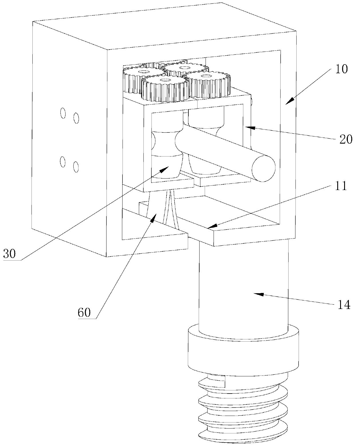
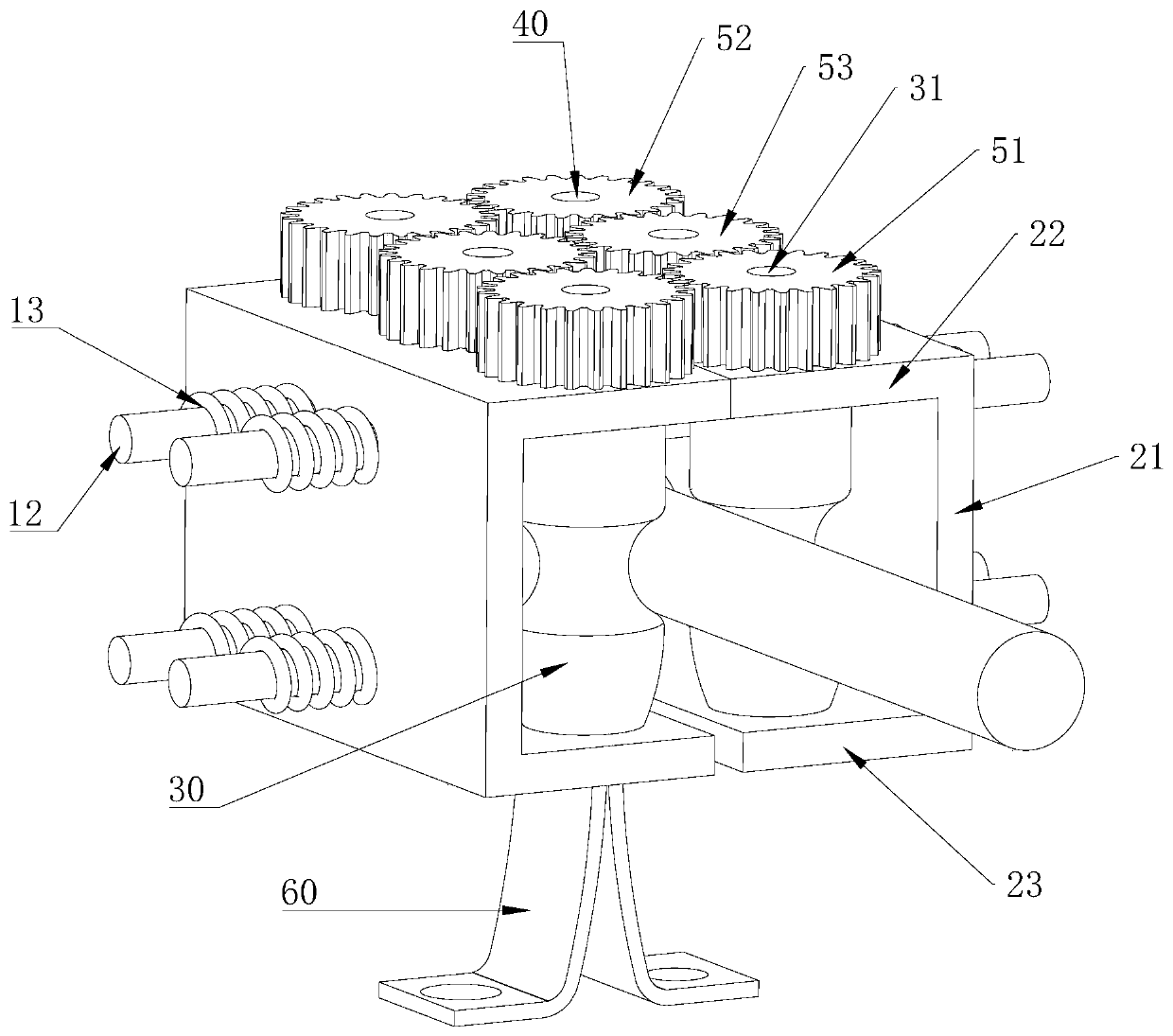
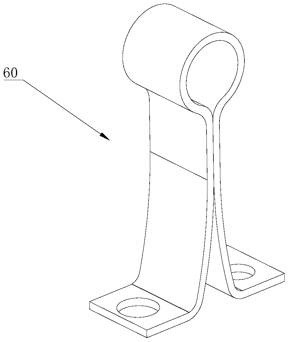
[0031] Such as figure 1 and figure 2 As shown, a traction system for overhead lines, the installation shell 10 is in the shape of a cuboid, the two ends of the installation shell 10 are provided with openings for the line to pass through, and one side wall of the installation shell 10 is provided with The line-entry gap 11 that runs through the two line-through gaps, the width of the line-entry gap 11 is greater than the width of the line, the installation shell 10 is provided with an elastic splint 60 for clamping the line, and the elastic splint 60 is bent and set. The closed end and the open end, the open end of the elastic splint 60 is connected to the line inlet gap 11; the clamping assembly (not marked in the figure) includes two supports 20 slidingly arranged in the installation shell 10, and the two supports The parts 20 are respectively located at both ends of the width direction of the line inlet gap 11, and the side of the two supporting parts 20 close to each oth...

Embodiment 2

[0038] A traction system for overhead lines such as figure 1 and Figure 5 As shown, a traction shaft 31 is rotationally connected between the upper and lower wheels, the traction wheel 30 is an eccentric traction wheel 32 provided with an eccentric hole, and the eccentric traction wheel 32 is fixed on the traction shaft through an eccentric hole 321 31. When the eccentric traction wheel 32 rolls along the line, it can generate certain pressure on the line, which increases the friction between the eccentric traction wheel 32 and the line on the one hand, and facilitates the rotation of the cleaning shaft 40; It can crush the hard ice on the line when ice is used, which is very convenient to use.

[0039] Preferably, when deicing, an eccentric eccentric traction wheel 32 can also be installed on the cleaning shaft 40 .

[0040] The rest of this embodiment is the same as that of Embodiment 1, and the features not explained in this embodiment are explained in Embodiment 1, and...

Embodiment 3

[0042] A traction system for overhead lines such as Figure 6 and Figure 7 As shown, the difference between this embodiment and Embodiment 1 is that the transmission member includes a synchronous belt 59 sheathed between the driving wheel and the driven wheel. Specifically, the upper plate 22 is provided with a bar-shaped installation groove 55 between the driving wheel and the driven wheel, and the installation rod 56 is arranged in the installation groove 55, and the installation rod 56 is provided with a sliding connection to adjust Shaft 57, the adjustment shaft 57 is rotatably connected with a buffer gear 54, the buffer gear 54 is meshed with the synchronous belt 59, the second spring 58 is sleeved on the installation rod 56, and the two ends of the second spring 58 The ends respectively abut against the groove wall of the installation groove 55 and the adjustment shaft 57 , and when the second spring 58 is in a natural state, the buffer gear 54 abuts against the synchr...


PUM


Abstract

The invention relates to the technical field of overhead lines, and particularly relates to a traction system for an overhead line. The traction system comprises an installation shell, wherein wire passing notches are formed in the two ends of the installation shell, a wire inlet notch is formed in the installation shell, an elastic clamping plate is arranged in the installation shell, the elasticclamping plate is arranged in a bent mode and provided with a closed end and an open end, and the open end of the elastic clamping plate is connected with the wire inlet notch; a clamping assembly which comprises two supporting pieces arranged in the installation shell in a sliding mode, wherein the two supporting pieces are located at the two ends of the wire inlet notch in the width direction respectively, traction wheels are rotationally borne on the sides, close to each other, of the two supporting pieces, first springs are arranged at the ends, away from each other, of the two supportingpieces, and the ends, away from the supporting pieces, of the first springs are connected with the inner wall of the installation shell; and a cleaning assembly which is arranged on the supporting pieces and used for cleaning sundries on the line. When the system moves along the line, the cleaning assembly can clean the sundries on the line, use is very convenient, physical power is not consumed,and the system can adapt to the line higher than the ground.

Description

technical field [0001] The invention relates to the technical field of overhead lines, in particular to a traction system for overhead lines. Background technique [0002] The overhead line is set at a high altitude. When there are kites, plastic bags and other sundries wrapped around the line, or when the line freezes in winter, it is necessary to follow the line to clean up. At present, during the operation process, the operator usually holds a long tool bar to clean it. Because the tool bar is long and heavy, it consumes physical strength, and it is very difficult for the staff to operate; at the same time, when the overhead line is too high, the general tool Pole may not reach. Contents of the invention [0003] The technical problem to be solved by the embodiments of the present invention is that it is very laborious and difficult to clean up the sundries of overhead lines. [0004] In order to solve the above technical problems, an embodiment of the present inventi...

Claims


Application Information

Patent Timeline
IPC IPC(8): H02G1/02
CPCH02G1/02
Inventor 顾光荣李明华丁志敏唐煊阳周仕炜袁一方杨诚杨琪冯鼎鹤
Owner GUIZHOU POWER GRID CO LTD
Why Eureka
Try Eureka