Environmentally-friendly efficient drying facility for bioengineering

A technology of biological engineering and drying equipment, applied in the directions of drying solid materials, drying goods processing, drying gas arrangement, etc., can solve the problems of insufficient drying, accumulation into lumps, low efficiency, etc., to reduce operation trouble, reduce trouble, Simple and convenient operation

Pending Publication Date: 2021-04-13
陈春娣
View PDF3 Cites 0 Cited by
  • Summary
  • Abstract
  • Description
  • Claims
  • Application Information

AI Technical Summary

Problems solved by technology

[0005] In order to overcome the shortcomings of the existing bioengineering drying treatment equipment, such as high energy consumption, low efficiency, and the fact that materials are easily accumulated into blocks in the equipment and cannot be fully dried, the technical problem of the present invention is: to provide a high-efficiency and resource-saving Environmentally friendly and efficient drying equipment for bioengineering

Method used


Image

  • Environmentally-friendly efficient drying facility for bioengineering
  • Environmentally-friendly efficient drying facility for bioengineering
  • Environmentally-friendly efficient drying facility for bioengineering

Examples


Embodiment 1

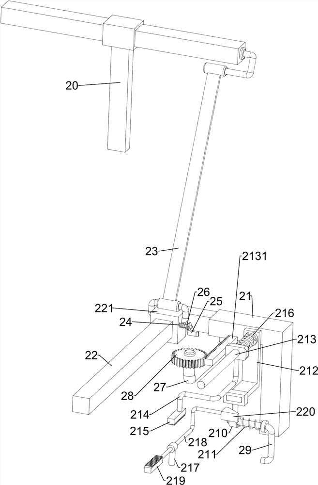
[0030] A kind of environment-friendly high-efficiency drying equipment for bioengineering, such as Figure 1 to Figure 4 As shown, it includes a frame 1, a box body 2, a shaking assembly 3, a material blocking assembly 4 and a heating assembly 5. The upper side of the frame 1 is provided with a box body 2, and the box body 2 is provided with a shaking assembly 3. The box body The upper side of the box body 2 is provided with a blocking assembly 4, and the left side of the box body 2 is provided with a heating assembly 5.

[0031] When it is necessary to dry the bioengineering material, control the stopper component 4 to open, then place the material in the box body 2, then close the stopper component 4, and then control the shaking component 3 to operate, so that the gas in the box body 2 The circulation is faster, and the heating component 5 can also be activated at the same time, thereby increasing the temperature in the box body 2, thereby speeding up the drying of the mate...

Embodiment 2

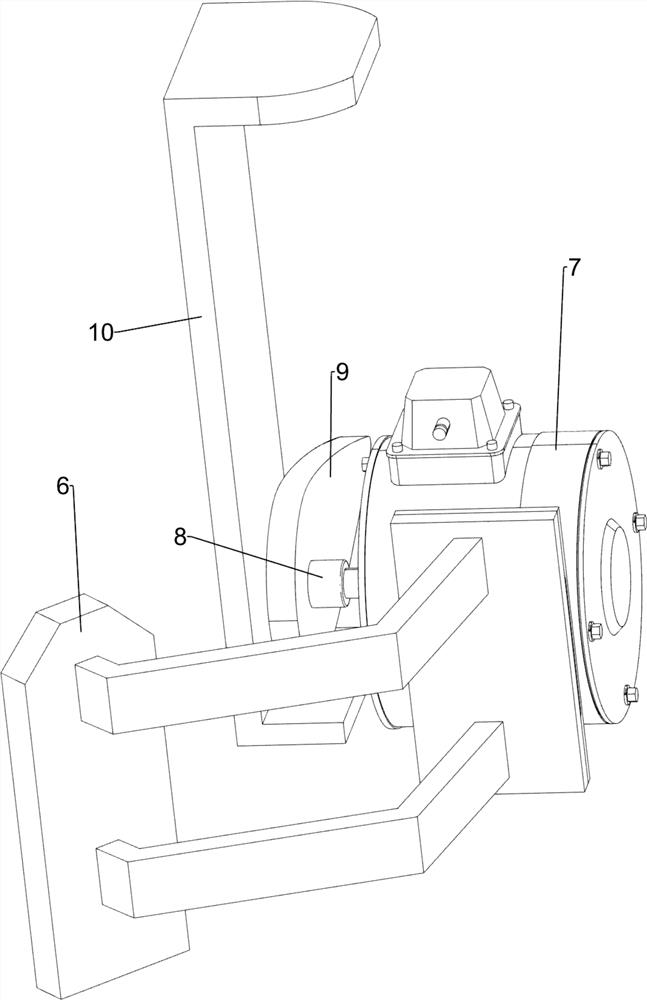
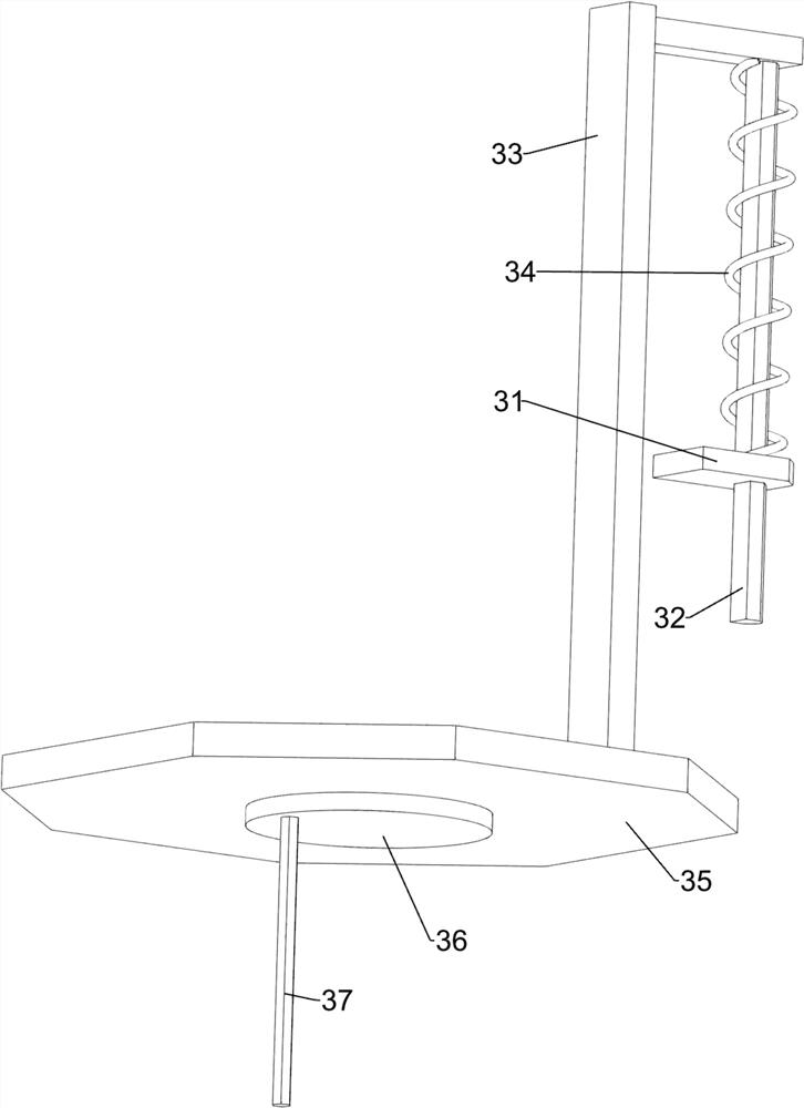
[0039] On the basis of Example 1, such as Figure 5 , Image 6 and Figure 7 As shown, it also includes a second mounting frame 6, a motor 7, a second rotating shaft 8, a cam 9 and a contact frame 10, and the rear side of the box body 2 is fixedly connected with a second mounting frame 6 by bolts, and on the second mounting frame 6 A motor 7 is provided, the output shaft of the motor 7 is connected with a second shaft 8, the second shaft 8 is keyed with a cam 9, the lower side of the first slide bar 32 is welded with a contact frame 10, and the contact frame 10 cooperates with the cam 9 .

[0040] When it is necessary to dry the bioengineering material, start the motor 7, and the motor 7 will drive the second rotating shaft 8 to rotate, thereby causing the cam 9 to rotate. When the cam 9 rotates to contact with the contact frame 10, the contact frame will be 10 moves downwards, thereby causing the first sliding rod 32 to move downwards. When the cam 9 rotates until it is no...


PUM


Abstract

The invention relates to drying equipment, in particular to an environmentally-friendly efficient drying facility for bioengineering. The technical problem to be solved is to provide the efficient energy-saving environmentally-friendly drying facility for the bioengineering. The environmentally-friendly efficient drying facility for the bioengineering comprises a machine frame, a box body, a shaking assembly, a material blocking assembly and a heating assembly, wherein the box body is installed on the machine frame, the shaking assembly is installed on the box body, the material blocking assembly is installed on the box body, and the heating assembly is installed on the box body. According to the environmentally-friendly efficient drying facility for the bioengineering, a motor is controlled, then a first sliding rod can automatically move, the first sliding rod does not need to be manually controlled to move, and therefore the physical strength of a worker does not need to be consumed, and the working efficiency is improved. The environmentally-friendly efficient drying facility for the bioengineering is provided with a push rod, dried materials can be taken out by controlling the push rod to rotate, then the operation can be easier and more convenient, and then the burden of the worker is reduced.

Description

technical field [0001] The invention relates to a drying device, in particular to an environment-friendly and high-efficiency drying device for bioengineering. Background technique [0002] By mastering the basic theories of biotechnology and its industrialization, such as scientific principles, technological processes, and engineering design, bioengineering cultivates an engineering technology that can be engaged in design, production management, new technology research, and new product development in the field of biotechnology and engineering. [0003] Drying treatment is often used in bioengineering. The general drying treatment equipment evaporates and escapes the water in the material by heating. However, the existing bioengineering drying treatment equipment consumes a lot of energy and has low efficiency. The equipment accumulates into lumps and cannot be fully dried, so it needs to consume more resources for heating and drying. [0004] Therefore, it is necessary to...

Claims


Application Information

Patent Timeline
Patent Type & Authority Applications(China)
IPC IPC(8): F26B11/14F26B21/00F26B25/00F26B25/02F26B25/04
CPCF26B11/14F26B21/001F26B25/002F26B25/04F26B25/02
Inventor 陈春娣
Owner 陈春娣
Why Eureka
Try Eureka