Workbench for laser engraving machine

A laser engraving machine and workbench technology, which is applied to laser welding equipment, manufacturing tools, metal processing equipment, etc., can solve the problems of inaccurate placement, inaccurate engraving position, and inability to engrave, so as to improve accuracy, The effect of improving efficiency

Active Publication Date: 2020-04-21
浙江威克环境艺术工程有限公司
View PDF6 Cites 1 Cited by
  • Summary
  • Abstract
  • Description
  • Claims
  • Application Information

AI Technical Summary

Problems solved by technology

[0004] When the existing laser engraving machine engraves this kind of plate, it needs to manually place the position of the plate accurately, and then determine the origin of the engraving, and then it can accurately engrave each plate. After the engraving is completed, Then manually remove the boards on the top of the workbench one by one. Since the top of the workbench of the existing engraving machine is a horizontal plane, it is necessary to manually place the positions of each board, and the placement position is often inaccurate. Therefore, the problem of inaccurate engraving position is prone to occur, and manual engraving cannot be carried out during the process of loading and unloading, and there is a problem of low engraving efficiency

Method used


Image

  • Workbench for laser engraving machine
  • Workbench for laser engraving machine
  • Workbench for laser engraving machine

Examples


Embodiment

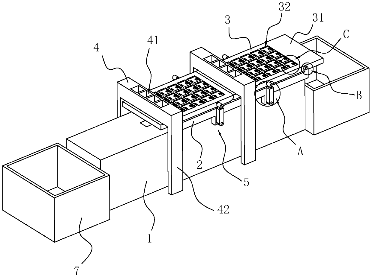
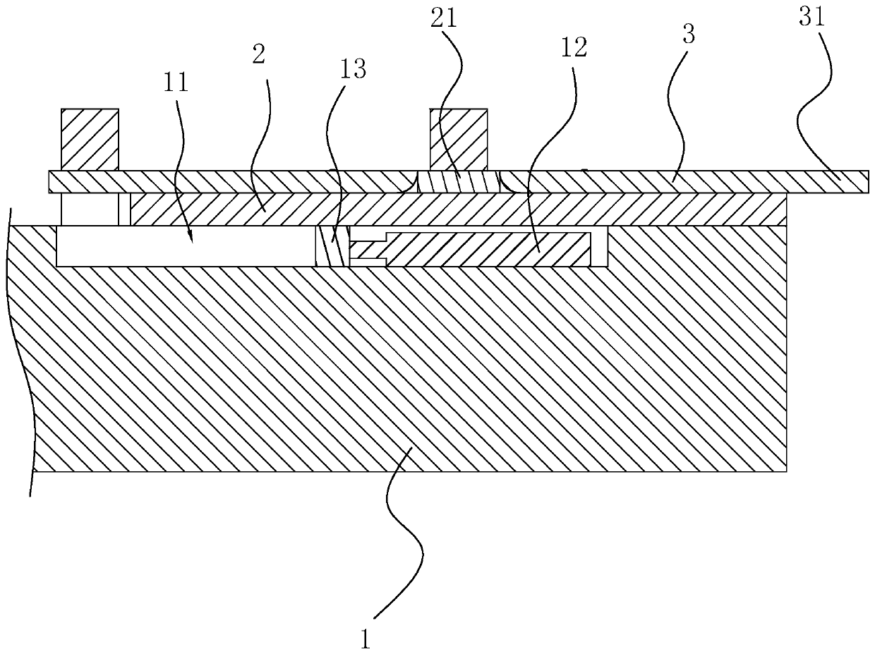
[0037] Embodiment: A workbench for laser engraving machine, including a base 1, a sliding plate 2 arranged on the top of the base 1, two supporting plates 3 arranged on the top of the sliding plate 2, and a baffle 21 arranged between the two supporting plates 3 , respectively fixedly connected to the limiting plate 31 on the side where the two support plates 3 are away from each other and the two collection boxes 7 arranged at the two ends of the base 1; The same as the length direction of the top of the base 1, the sliding plate 2 slides along the length direction of the sliding plate 2 on the top of the base 1, the two support plates 3 are horizontally arranged and the length direction of the two support plates 3 is the same as the length direction of the sliding plate 2, The ends of the two supporting plates 3 facing away from each other are flush with the two ends of the sliding plate 2 . The top and the bottom of the baffle plate 21 are flush with the top and the bottom o...


PUM


Abstract

The invention discloses a workbench for a laser engraving machine, relates to the technical field of plate engraving, solves the problem of low plate engraving efficiency in the prior art. The workbench comprises a base, a sliding plate arranged at the top of the base and two supporting plates arranged at the top of the sliding plate; a plurality of limiting grooves are formed in the top of the supporting plate, and the limiting grooves are identical to the plates in shape and size. During engraving, plates are put into the limiting grooves of the two supporting plates, then, one supporting plate is slid to move to the position below an engraving head for engraving, after the plate on the supporting plate is engraved, the plate is cut, when the engraving head rotates, the engraving head slides towards the direction deviating from the other supporting plate, so that the other supporting plate is located under the engraving head for engraving, the engraved plate in the supporting plate is discharged during engraving, and a new plate is placed. The plate is engraved while feeding and discharging are conducted, and the engraving efficiency is improved.

Description

technical field [0001] The invention relates to the technical field of plate engraving, more specifically, it relates to a workbench for a laser engraving machine. Background technique [0002] Laser engraving machine, as the name implies, is a kind of equipment that uses laser to engrave materials that need to be engraved. Compared with mechanical engraving machines, laser engraving machines are used in a wider range, and the engraving accuracy is higher, and the engraving speed is faster. [0003] A plate that needs to be engraved on the surface. The plate is rectangular and the shape of the plate is small. When engraving, several plates are placed on the workbench of the laser engraving machine, and the plates are arranged on the workbench. [0004] When the existing laser engraving machine engraves this kind of plate, it needs to manually place the position of the plate accurately, and then determine the origin of the engraving, and then it can accurately engrave each pl...

Claims


Application Information

Patent Timeline
IPC IPC(8): B23K26/362B23K26/70
CPCB23K26/362B23K26/70B23K26/702
Inventor 宫威郑叶萍
Owner 浙江威克环境艺术工程有限公司
Why Eureka
Try Eureka