
Automatic abrasive paper mounting device

An automatic installation and sandpaper technology, which is applied in the direction of grinding heads, grinding machine parts, metal processing equipment, etc., can solve the problems that have not yet been provided, excessive wear of sandpaper, and grinding machines cannot work.

Active Publication Date: 2020-04-21
SHANGHAI FANUC ROBOTICS
View PDF10 Cites 1 Cited by
  • Summary
  • Abstract
  • Description
  • Claims
  • Application Information

AI Technical Summary

Problems solved by technology

[0003] In the prior art, the sandpaper is prone to excessive wear, so it is necessary to replace the sandpaper, and when installing the sandpaper, it must be ensured that the sandpaper holes in the sandpaper correspond to the grinding disk holes in the grinding disc, otherwise the grinding machine after installing the sandpaper cannot To carry out the work, the prior art has not provided a device that can automatically install the sandpaper on the grinding disc at a certain angle of the sandpaper hole, so as to realize the one-to-one correspondence between the sandpaper holes and the grinding disc holes

Method used


Image

  • Automatic abrasive paper mounting device
  • Automatic abrasive paper mounting device
  • Automatic abrasive paper mounting device

Examples


Embodiment Construction

[0047] The following will clearly and completely describe the technical solutions in the embodiments of the present invention with reference to the accompanying drawings in the embodiments of the present invention. Obviously, the described embodiments are only some, not all, embodiments of the present invention. Based on the embodiments of the present invention, all other embodiments obtained by persons of ordinary skill in the art without creative efforts fall within the protection scope of the present invention.

[0048] It should be noted that, in the case of no conflict, the embodiments of the present invention and the features in the embodiments can be combined with each other.

[0049] The present invention will be further described below in conjunction with the accompanying drawings and specific embodiments, but not as a limitation of the present invention.

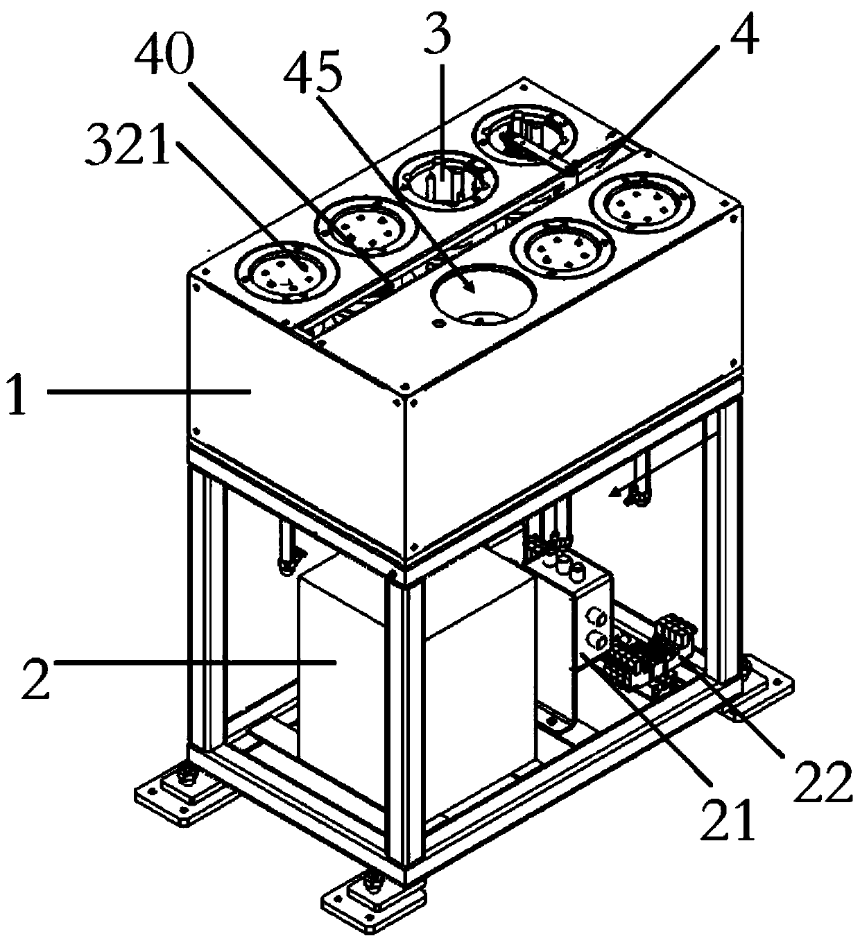
[0050] An automatic sandpaper installation device such as figure 1 As shown, it is used for the grinding device...


PUM


Abstract

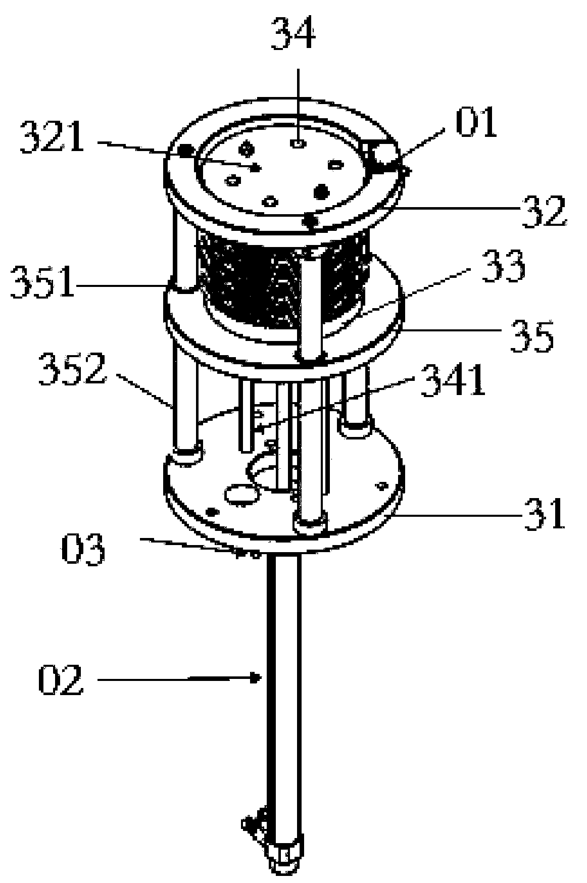
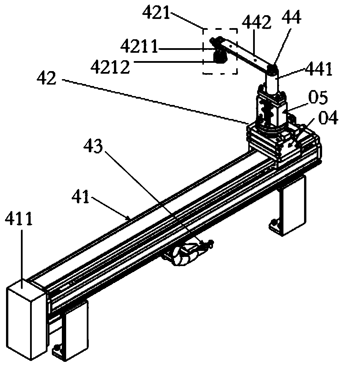
The invention relates to the field of dry type grinding, and particularly relates to an automatic abrasive paper mounting device. The automatic abrasive paper mounting device internally comprises a containing space, and further comprises a control mechanism, a plurality of abrasive paper spaces, a plurality of first photoelectric switches and a plurality of first air cylinders, wherein the controlmechanism is arranged below the containing space and connected with a grinding device; the abrasive paper spaces are evenly divided in the containing space; each abrasive paper space comprises an abrasive paper bearing plate parallel to the bottom face of the abrasive paper space and used for containing abrasive paper and an abrasive paper space top face coinciding with the top face of the containing space; the top face of each abrasive paper space is provided with a first opening matched with the abrasive paper; the first photoelectric switches correspond to the abrasive paper spaces in a one-to-one manner and are arranged at the first openings, and the first photoelectric switches are connected with the control mechanism; and the first air cylinders correspond to the abrasive paper spaces in a one-to-one manner, one end of each first air cylinder is connected with the control mechanism, and the other end of each first air cylinder stretches into the corresponding abrasive paper space and is connected with the corresponding abrasive paper bearing plate. According to the technical scheme, the automatic abrasive paper mounting device has the beneficial effects that the abrasive paper is automatically mounted on a grinding disc, and one-to-one correspondence of abrasive paper holes and grinding disc holes is achieved.

Description

technical field [0001] The invention relates to the field of dry grinding, in particular to an automatic sandpaper installation device. Background technique [0002] At present, when the workpiece is polished, a grinding machine is often used for grinding, and sandpaper is set on the grinding disc of the grinding machine. The grinding disc has a plurality of grinding disc holes, and the sand paper has multiple sandpaper holes. One-to-one correspondence can realize dust removal during the grinding process. [0003] In the prior art, the sandpaper is prone to excessive wear, so it is necessary to replace the sandpaper, and when installing the sandpaper, it must be ensured that the sandpaper holes in the sandpaper correspond to the grinding disk holes in the grinding disc, otherwise the grinding machine after installing the sandpaper cannot For work, the prior art has not yet provided a device that can automatically install the sandpaper on the grinding disc at a determined sa...

Claims


Application Information

Patent Timeline
Patent Type & Authority Applications(China)
IPC IPC(8): B24B41/00
CPCB24B41/002
Inventor 汪相龙王冉芳欧洋王志龙伊春明
Owner SHANGHAI FANUC ROBOTICS
Learn More