
Bionic obstacle-crossing wall-climbing robot

A wall-climbing robot, bionic technology, applied in the field of robotics, can solve the problems that cannot be used for climbing walls, robots cannot walk on the line, etc., and achieve the effect of increasing stability

Active Publication Date: 2020-04-21
HARBIN UNIV
View PDF5 Cites 2 Cited by
  • Summary
  • Abstract
  • Description
  • Claims
  • Application Information

AI Technical Summary

Problems solved by technology

In road conditions with obstacles, ravines or steps, the obstacle-riding wheel mounting frame rotates relative to the bracket through the rotating shaft, the obstacle-riding wheel follows the obstacle-riding wheel mounting frame to rotate and crosses obstacles, ravines or to the top of the step, and passes through the obstacle The wheel driving mechanism drives the obstacle-crossing wheel to rotate, and it rotates together with the first road wheel or the first road wheel and the second road wheel, so that the wheeled obstacle-crossing robot can cross obstacles, ravines and steps; but the robot cannot walk on the line and cannot for wall climbing

Method used


Image

  • Bionic obstacle-crossing wall-climbing robot
  • Bionic obstacle-crossing wall-climbing robot
  • Bionic obstacle-crossing wall-climbing robot

Examples


specific Embodiment approach 1

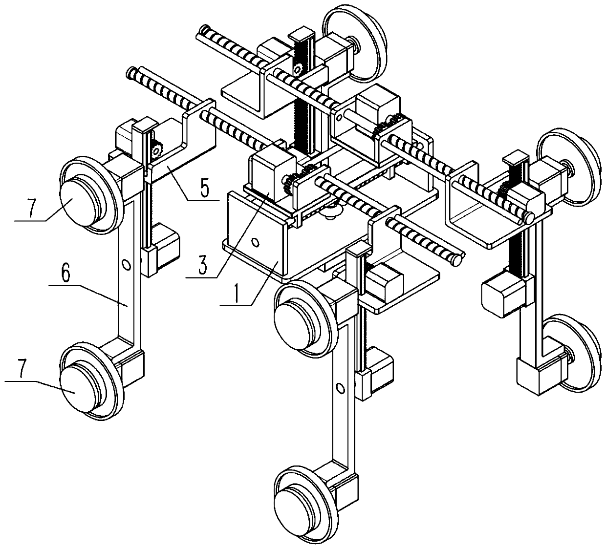
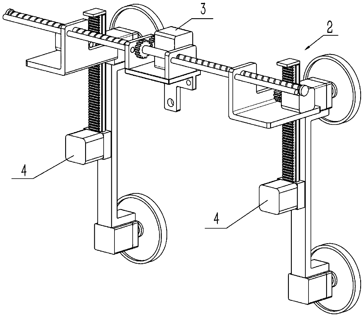
[0029] like Figure 1-8 As shown, a bionic obstacle-climbing robot includes a center-of-gravity adjustment mechanism 1 and a bionic obstacle-climbing assembly 2. Two bionic obstacle-climbing assemblies 2 are provided and are connected to the center-of-gravity adjustment mechanism 1. The adjusting mechanism 1 adjusts the distance between two bionic obstacle climbing components 2 . The bionic obstacle-climbing assembly 2 is used to imitate a person using both arms to support, knees and calves to climb mechanically, so as to complete the obstacle-climbing action. Two bionic obstacle-climbing assemblies 2 drive the whole device to move and overcome obstacles Or wall-climbing movement, when increasing the distance between the two obstacle-climbing wall-climbing components 2 and the adjustment mechanism 1, the stability of the movement can be increased, or adapt to the passages with different widths or adapt to the obstacles formed by two beam structures with different widths . Du...

specific Embodiment approach 2

[0031] like Figure 1-8 As shown, the center of gravity adjustment mechanism 1 synchronously adjusts the distance between two bionic obstacle climbing components 2 . During synchronous adjustment, the center of gravity adjustment mechanism 1 can always be at the center of the two bionic obstacle-climbing components 2 to maintain the stability of the entire robot movement.

specific Embodiment approach 3

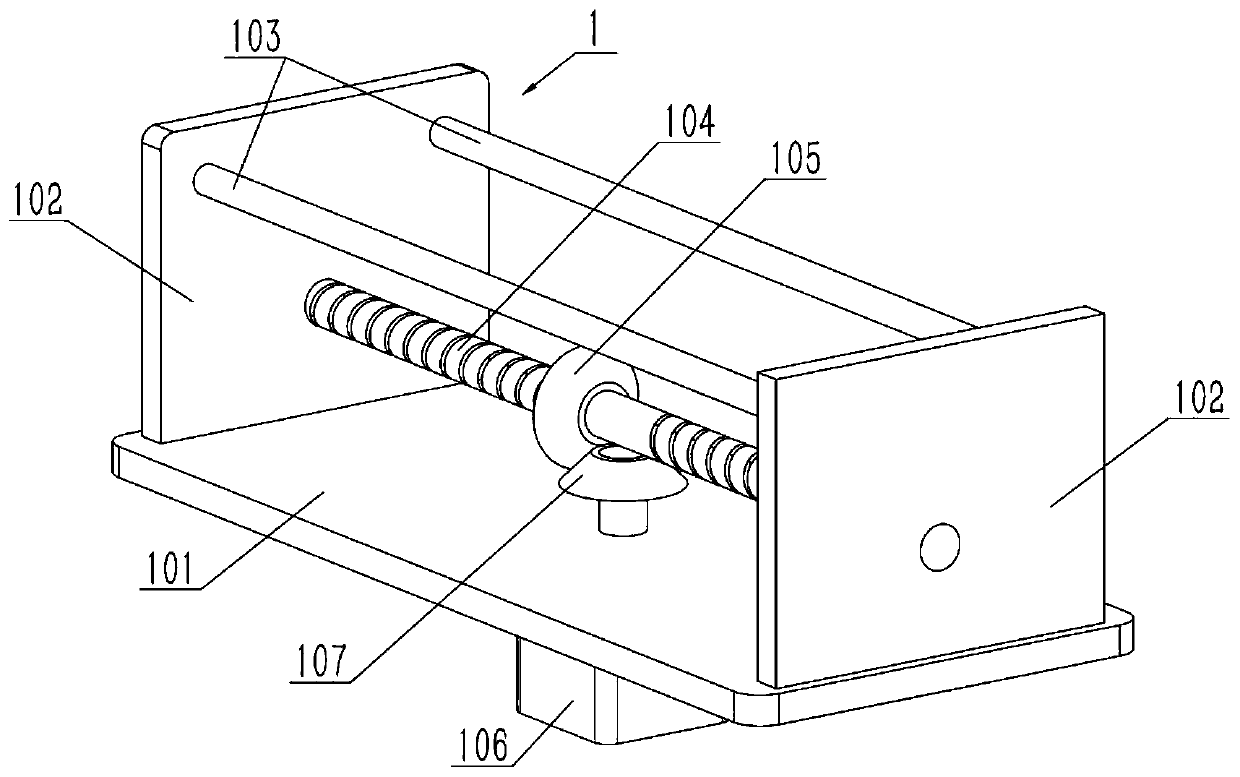
[0033] like Figure 1-8 As shown, the center-of-gravity adjustment mechanism 1 includes a base plate body I101, a shaft seat I102, a round steel I103, a bidirectional screw I104, a helical gear I105, a motor I106 and a helical gear II107, and the two sides of the upper end of the base plate body I101 are respectively fixed with a shaft Seat I102, the two ends of the round steel I103 are respectively fixed on the upper side of the two shaft seats I102, the two ends of the two-way lead screw I104 are respectively connected to the lower side of the two shaft seats I102, and the helical gear I105 is fixed on the two-way screw In the middle of the bar I104, the motor I106 is fixedly connected to the lower end of the substrate body I101, the output shaft of the motor I106 is connected to the substrate body I101 in rotation, the upper end of the output shaft of the motor I106 is fixedly connected to the helical gear II107, and the helical gear I105 and the helical gear II107 are meshe...


PUM


Abstract

The invention relates to a robot, in particular to a bionic obstacle-crossing wall-climbing robot. The robot comprises a gravity center adjusting mechanism and a bionic obstacle-crossing wall-climbingassembly, and four sets of arm-leg mechanisms can simulate the wall-climbing action of two arms and two legs of a person; the distance between the two arm-leg mechanisms on any side is adjustable, sothat the movement stability of the robot is improved or the robot can conveniently pass through a limited space; the robot can move on two lines by inversely clamping the walking groove on the lines,and when one line encounters an obstacle in the advancing process, the robot can be separated from the obstacle by lifting the arm-leg mechanism where a walking wheel II encounters an obstacle is located.

Description

technical field [0001] The invention relates to a robot, in particular to a bionic obstacle-climbing robot. Background technique [0002] For example, a wheeled obstacle-surmounting robot whose publication number is CN109178140A includes: a bracket, an obstacle-overriding wheel, an obstacle-overriding wheel mounting frame, an obstacle-overriding wheel driving mechanism, an obstacle-overriding wheel steering drive mechanism, a first traveling wheel, a first traveling wheel The steering drive mechanism, the second road wheel, the second road wheel steering drive mechanism and the two road wheel drive mechanisms, the bracket includes: the first branch pipe, the second branch pipe and the third branch pipe, the first branch pipe and the second branch pipe are relatively arranged at the In one plane, one end of the third branch pipe is installed on the first branch pipe. In road conditions with obstacles, ravines or steps, the obstacle-riding wheel mounting frame rotates relativ...

Claims


Application Information

Patent Timeline
Patent Type & Authority Applications(China)
IPC IPC(8): B62D57/024
CPCB62D57/024
Inventor 孙英杰
Owner HARBIN UNIV
Learn More