Intelligent food packaging execution equipment
A technology for food packaging and execution equipment, which is applied in the directions of packaging, transportation and packaging, and types of packaging items, and can solve problems such as unsmooth coordination of production links and power waste.
- Summary
- Abstract
- Description
- Claims
- Application Information
AI Technical Summary
Problems solved by technology
Method used
Image

Examples
specific Embodiment approach 1
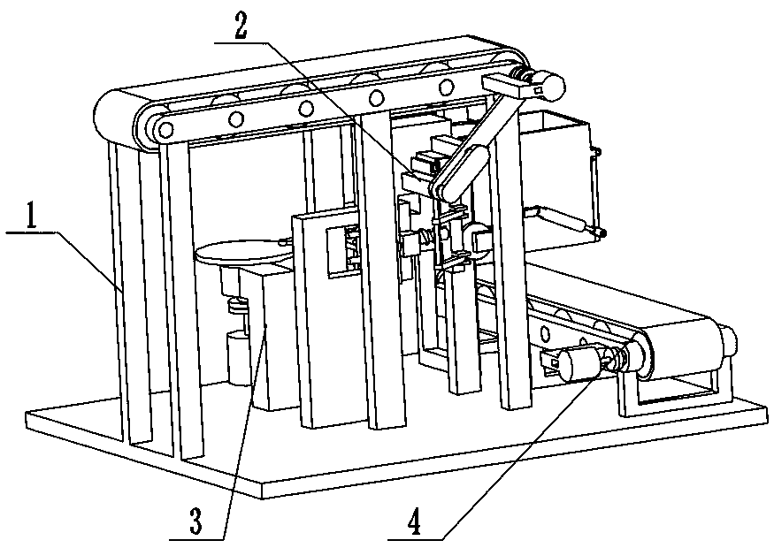
[0035] Combine below figure 1 , figure 2 , image 3 , Figure 4 , Figure 5 , Image 6 , Figure 7 , Figure 8 , Figure 9 , Figure 10 , Figure 11 , Figure 12 , Figure 13 , Figure 14 , Figure 15 , Figure 16 , Figure 17 , Figure 18 , Figure 19 Describe this embodiment. The present invention relates to a packaging device, more specifically, an intelligent food packaging execution device, including a feeding mechanism 1, a starting and unloading mechanism 2, a box feeding mechanism 3, and a conveyor belt mechanism 4. The equipment can be based on etc. Add food to the box by weight, the equipment can stop adding food when adding food to the box, the equipment can automatically send the box, and the equipment can transport the box away.
[0036] The feeding mechanism 1 is connected with the starting blanking mechanism 2 , the feeding mechanism 1 is connected with the box feeding mechanism 3 , and the feeding mechanism 1 is connected with the conveyor bel...
specific Embodiment approach 2
[0038] Combine below figure 1 , figure 2 , image 3 , Figure 4 , Figure 5 , Image 6 , Figure 7 , Figure 8 , Figure 9 , Figure 10 , Figure 11 , Figure 12 , Figure 13 , Figure 14 , Figure 15 , Figure 16 , Figure 17 , Figure 18 , Figure 19 Describe this embodiment, this embodiment will further explain Embodiment 1, the described feeding mechanism 1 includes a transmission mechanism 1-1, a belt 1-2, a movable wheel mechanism 1-3, a driving mechanism 1-4, a transmission mechanism 1- 1 is flexibly connected with the belt 1-2, the transmission mechanism 1-1 is in contact with the movable wheel mechanism 1-3, and the movable wheel mechanism 1-3 is connected with the driving mechanism 1-4; the transmission mechanism 1-1 includes a base 1-1 -1, outrigger 1-1-2, tail roller 1-1-3, intermediate drive roller 1-1-4, head roller 1-1-5, passive disc with holes 1-1-6, With bearing frame 1-1-7, base 1-1-1 is connected with outrigger 1-1-2, outrigger 1-1-2 is c...
specific Embodiment approach 3
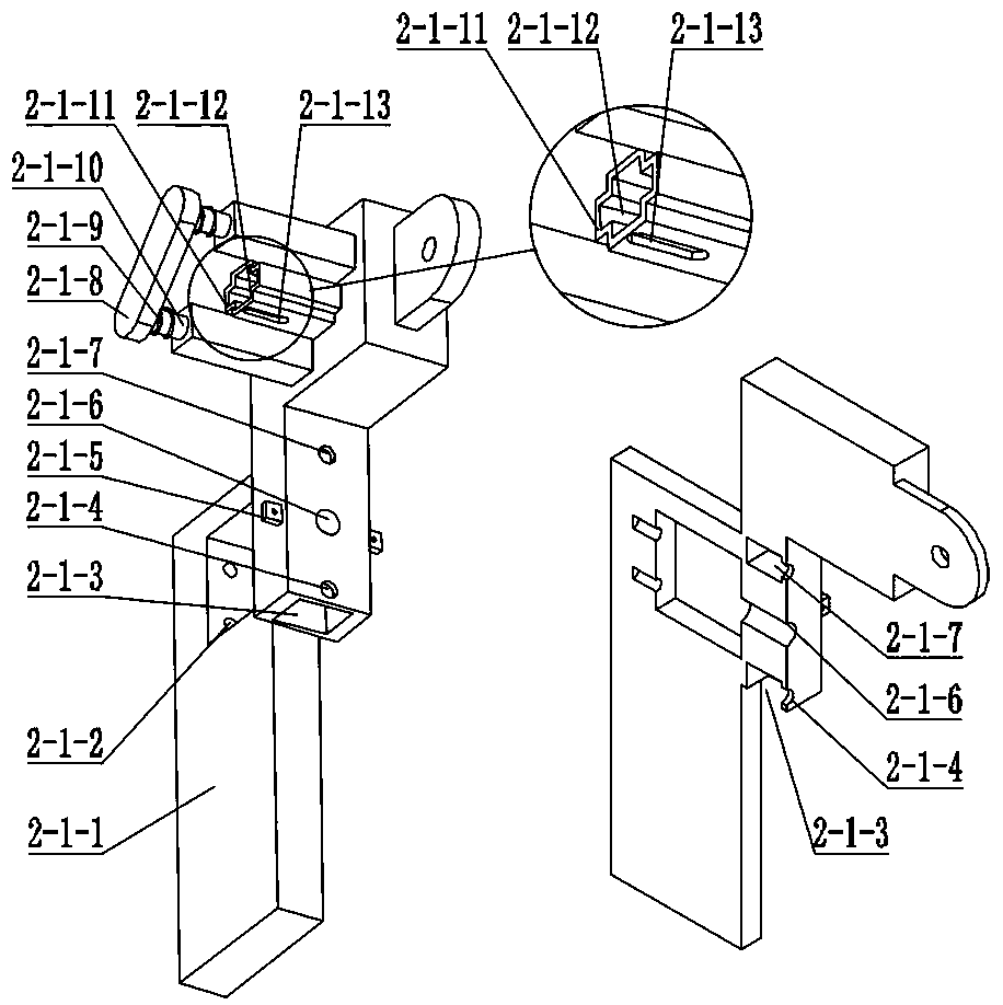
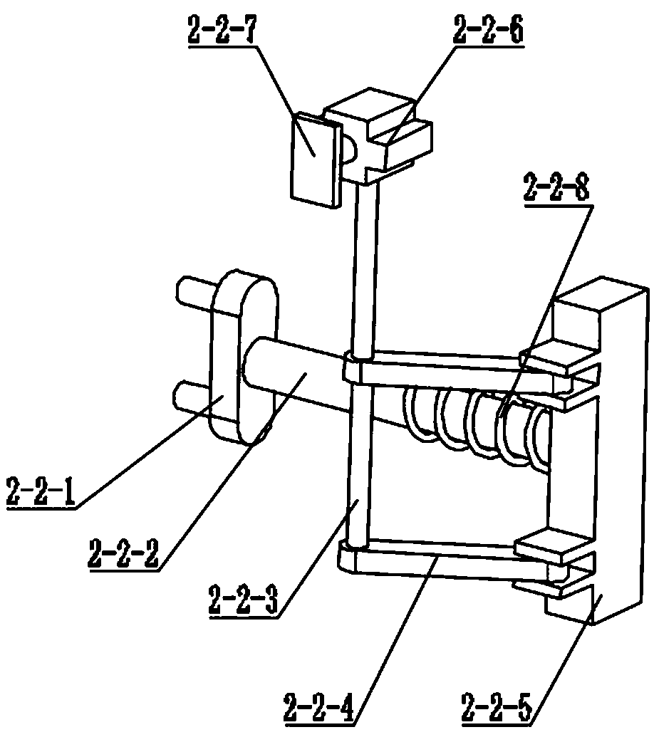
[0040] Combine below figure 1 , figure 2 , image 3 , Figure 4 , Figure 5 , Image 6 , Figure 7 , Figure 8 , Figure 9 , Figure 10 , Figure 11 , Figure 12 , Figure 13 , Figure 14 , Figure 15 , Figure 16 , Figure 17 , Figure 18 , Figure 19Describe this embodiment, this embodiment will further explain the first embodiment, the starting and unloading mechanism 2 includes a trigger support mechanism 2-1, a pressure movable seat mechanism 2-2, a threaded rod with a handle 2-3, a smooth column 2-4, the linkage mechanism 2-5, the gravity hopper mechanism 2-6, the gate mechanism 2-7, the pretightening force adjustment mechanism 2-8, the trigger support mechanism 2-1 is slidingly connected with the pressure movable seat mechanism 2-2, The threaded rod 2-3 with handle is threadedly connected with the trigger support mechanism 2-1, the smooth column 2-4 is connected with the threaded rod 2-3 with handle, and the smooth column 2-4 is rotationally connected ...
PUM
 Abstract
Description
Claims
Application Information