Curtain wall multi-direction multi-angle adjusting support
A technology for adjusting brackets and multi-angles, applied to walls, building components, buildings, etc., can solve the problems of simplified structure of hidden frame glass curtain wall, unfavorable stability of building body, unstable installation, etc., and achieve high-precision butt joint sealing treatment, structure Simple, easy to mass-produce the effect of production
- Summary
- Abstract
- Description
- Claims
- Application Information
AI Technical Summary
Problems solved by technology
Method used
Image
Examples
Embodiment 1
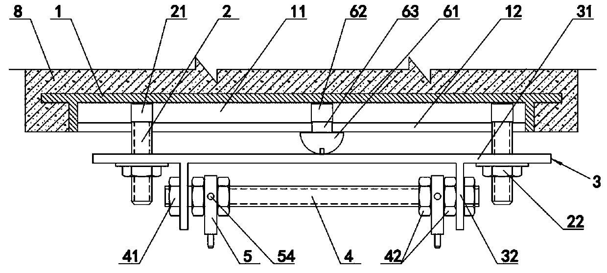
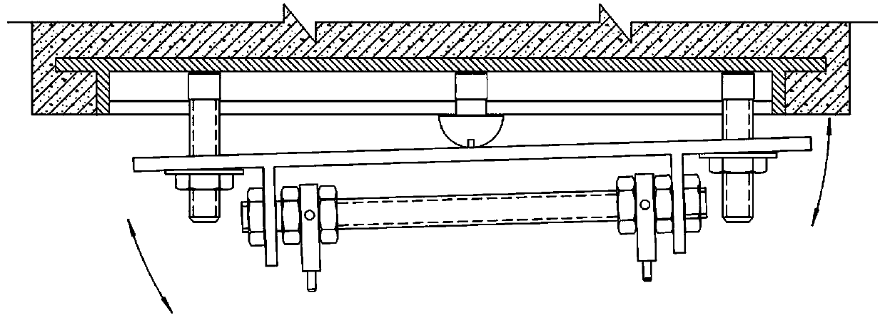
[0034] Embodiment 1: For the embedded parts arranged at intervals in advance during the pouring process of the exterior wall 8 of a high-rise building, the position spacing of each embedded part should be equal, the height should be the same, and all should be on the same horizontal plane, and the outer ends should be on the same elevation. However, in fact, the position uncertainty deviation of each embedded part often exists when pouring the outer wall, which leads to the need for necessary adjustments during the installation of the curtain wall. Aiming at the problem that the existing brackets used in the installation of curtain walls do not have the function of adjusting horizontal and vertical angles, this embodiment adopts a multi-directional and multi-angle adjusting bracket for curtain walls that can simultaneously adjust various angles and positions.
[0035] The embedded parts 11 used in this embodiment are as Figure 9 and Figure 10 As shown, it is a strip structu...
Embodiment 2
[0047] Embodiment 2: On the basis of Embodiment 1, a central spherical groove 65 is provided in the middle of the inner wall of the outer bracket 3 , and the central spherical body 61 is matched and fitted in the central spherical groove 65 . The position of the outer support 3 and the middle fulcrum 6 is constrained by the support spherical groove. Since the arc adjustment holes 34 on both sides of the outer support 3 have constrained the position of the corresponding root bolt 2, the present embodiment sets the structure of the middle support spherical groove 65. , can constrain the positions of the central spherical body 61 and the root bolts 2 on both sides together, that is, realize the synchronous translation function of the three, and ensure the synchronous movement of the three no matter where the outer ones move laterally. The middle fulcrum 6 is always located in the middle of the bolts 2 on both sides, that is, in the middle of the outer bracket 3, to ensure that bot...
Embodiment 3
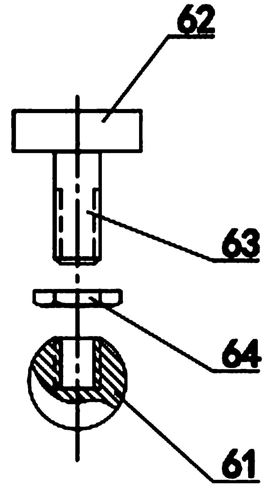
[0048] Embodiment 3: On the basis of Embodiment 1, the middle fulcrum 6 includes a middle support spherical body 61, a strip-shaped inner chuck 62 and a neck 63, and the strip-shaped inner chuck 62 is a rectangular body whose width is not greater than that of the outer narrow groove 12 width, the length of the rectangular body is greater than the width of the outer narrow groove 12 but less than the width of the inner wide groove 11, the strip-shaped inner chuck 62 is installed in the inner wide groove 11, the neck 63 is set in the outer narrow groove 12, and rotated 90 degrees . Further, a conjoined plate 7 is set on the outside of the root bolt 2 and the central fulcrum 6 at the same time, as Figure 12 As shown, positioning holes 71 are respectively provided on the conjoined plate for installing the corresponding root bolts 2 and the middle fulcrum 6, so as to connect the root bolts 2 on both sides and the middle fulcrum 6 as a whole. The position of the outer support 3 an...
PUM
 Abstract
Description
Claims
Application Information
 - R&D
- Intellectual Property
- Life Sciences
- Materials
- Tech Scout
- Unparalleled Data Quality
- Higher Quality Content
- 60% Fewer Hallucinations
Browse by: Latest US Patents, China's latest patents, Technical Efficacy Thesaurus, Application Domain, Technology Topic, Popular Technical Reports.
© 2025 PatSnap. All rights reserved.Legal|Privacy policy|Modern Slavery Act Transparency Statement|Sitemap|About US| Contact US: help@patsnap.com


