Pneumatic electromagnetic valve and flight vehicle

A pneumatic solenoid valve and aircraft technology, applied in the field of solenoid valves, to achieve the effect of low cost, good effect and simple structure

Active Publication Date: 2020-04-21
宁波天擎航天科技有限公司
View PDF6 Cites 6 Cited by
  • Summary
  • Abstract
  • Description
  • Claims
  • Application Information

AI Technical Summary

Problems solved by technology

[0005] The embodiment of the present invention provides a pneumatic solenoid valve, which aims to solve the problem of how to sa

Method used


Image

  • Pneumatic electromagnetic valve and flight vehicle
  • Pneumatic electromagnetic valve and flight vehicle
  • Pneumatic electromagnetic valve and flight vehicle

Examples


Embodiment 1

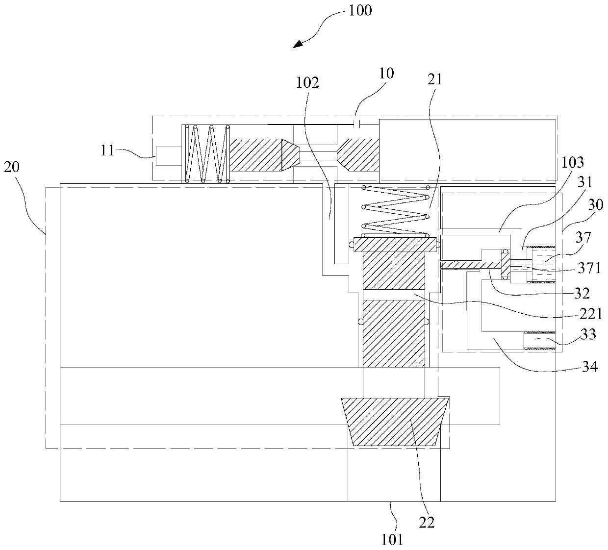
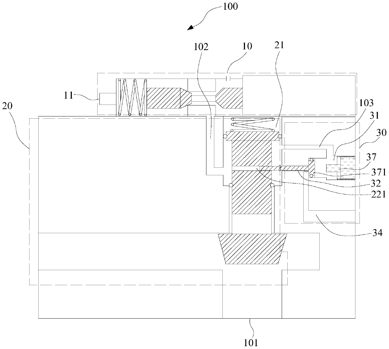
[0024] see Figure 1 to Figure 3 , the pneumatic solenoid valve 100 of the embodiment of the present invention is used in an aircraft, and the aircraft is connected to the liquid outlet 101 of the pneumatic solenoid valve 100 . The pneumatic solenoid valve 100 includes an air inlet portion 10 , a liquid inlet portion 20 and a fixing portion 30 . The intake portion 10 is provided with an intake port 11 . The liquid inlet part 20 includes a first cavity 21 and a first valve core 22 movably arranged in the first cavity 21 , the first cavity 21 communicates with the air inlet 11 through a first channel 102 , and the first valve core 22 It can move in the first cavity 21 to open or close the liquid outlet 101 . The fixing part 30 includes a second cavity 31 , a locking rod 32 detachably arranged in the second cavity 31 , a first blocking member 33 and a second channel 34 , the second cavity 31 and the first cavity 21 pass through The third channel 103 communicates, the clamping ...

Embodiment 2

[0037] see figure 1 , Figure 6 and Figure 7 Further, the fixed part 30 is also provided with a through groove 35, the fixed part 30 also includes a second blocking member 37, and the second blocking member 37 includes a push seat 371, a plug 373, and a spacer plug 373 and a push seat The connecting rod 372 of 371, the push seat 371 is connected with the clamping rod 32, and is movable relative to the connecting rod 372 and the plug 373, and the cross-sectional area of ​​the connecting rod 372 is less than the cross-sectional area of ​​the plug 373;

[0038] When the clamping rod 32 is disassembled, the connecting rod 372 and the plug 373 withstand the push seat 371, and the push seat 371 remains between the through groove 35 and the second cavity 31, so that the first cavity 21 and the second cavity 31 Not connected;

[0039] When retaining the rod 32, the rod 32 is inserted into the through groove 35, and when the first valve core 223 moves toward the second elastic memb...

Embodiment 3

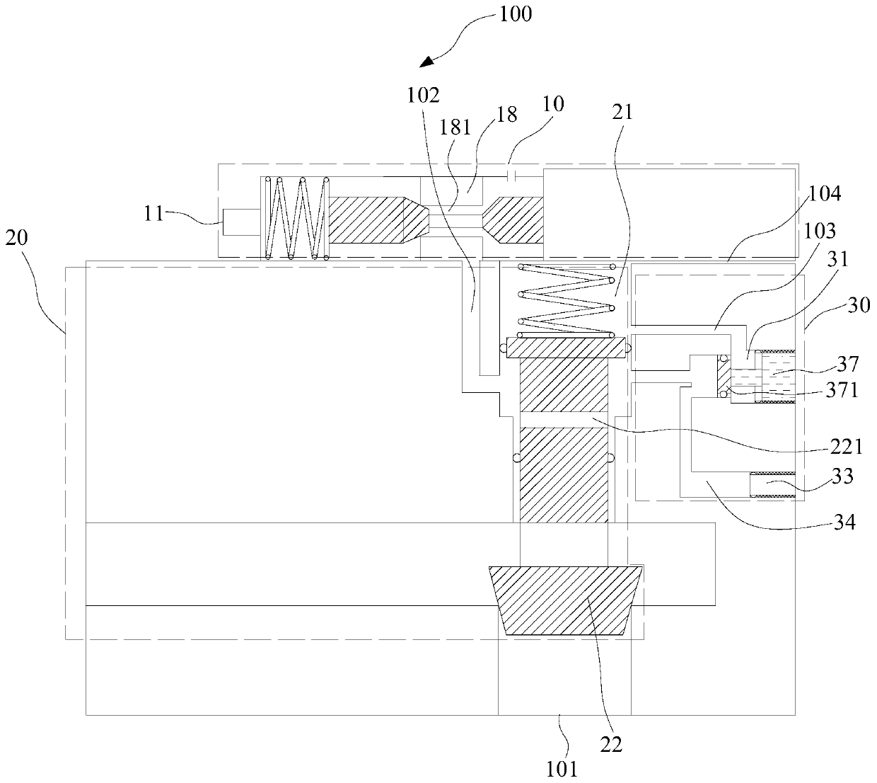
[0043] read on figure 1 and Figure 4 Further, the air intake part 10 also includes a retaining ring 18 arranged in the first housing 12, the retaining ring 18 is provided with an air intake passage 181, the push rod 14 passes through the air intake passage 181, the second valve core 13 and the The third spool 15 is respectively located on both sides of the intake passage 181. When the push rod 14 drives the second spool 13 and the third spool 15 to move simultaneously, the second spool 13 or the third spool 15 can be connected with the retaining ring. 18 contacts; when the second spool 13 is in contact with the retaining ring 18 and the third spool 15 is spaced from the retaining ring 18, the intake passage 181 is closed, and the intake port 11 is not connected to the first passage 102; when the second spool 13 is spaced from the retaining ring 18 and the third spool 15 is in contact with the retaining ring 18 , the intake passage 181 is opened, and the intake port 11 commun...


PUM


Abstract

The invention belongs to the field of electromagnetic valves, and provides a pneumatic electromagnetic valve and a flight vehicle. A liquid outlet of the pneumatic electromagnetic valve is connected with the flight vehicle, the pneumatic electromagnetic valve comprises a gas inlet part, a liquid inlet part and a fixing part, the gas inlet part is provided with a gas inlet, the liquid inlet part comprises a first cavity and a first valve core, the first cavity communicates with the gas inlet through a first channel, and the first valve core can move in the first cavity so as to open or close aliquid outlet; the fixing part comprises a second cavity, a clamping rod, a first blocking piece and a second channel, the second cavity communicates with the first cavity through a third channel, andthe clamping rod and the first blocking piece are located at the two ends of the second channel correspondingly; a clamping groove is formed in the first valve core, when the first blocking piece isdetached, the clamping rod can move in the second cavity to penetrate through the clamping groove, and the first valve core is fixed to the first cavity so as to keep the liquid outlet to be open; andwhen the clamping rod is detached, the first valve core is introduced along with the gas so as to open the liquid outlet, or is discharged along with the gas so as to close the liquid outlet. The different demands of the flight vehicle under different states can be met.

Description

technical field [0001] The invention belongs to the field of solenoid valves, in particular to a pneumatic solenoid valve and an aircraft. Background technique [0002] Before the official flight of the aircraft, a ground test is required to open or close the valve multiple times to ensure that the valve and the aircraft can work normally, that is, the valve needs to have the function of multiple switches to meet the needs of the ground test. [0003] During the official flight of the aircraft, the valve needs to be kept open to continuously obtain propellant to ensure normal flight. Therefore, it is necessary to continuously supply electric energy and air source to the valve to keep the valve open. If the valve is closed and the aircraft cannot get the supply of propellant, then the entire aircraft system will be in a state of inoperability, and the aircraft cannot fly normally. [0004] At present, the following two methods are generally used to meet the needs of the airc...

Claims


Application Information

Patent Timeline
IPC IPC(8): F16K1/38F16K1/32F16K27/02F16K31/06F16K31/12F16K35/02
CPCF16K1/32F16K1/38F16K27/0254F16K27/029F16K31/0655F16K31/0675F16K31/12F16K35/027
Inventor 不公告发明人
Owner 宁波天擎航天科技有限公司
Why Eureka
Try Eureka