
Touch device and touch display device thereof

A technology of touch display devices and touch devices, which is applied in the directions of instruments, computing, and electrical digital data processing, etc., and can solve the problems of occupying frame area, signal deterioration, and wiring not being too narrow, etc., to achieve the effect of narrow frame

Active Publication Date: 2020-04-21
SHANGHAI TIANMA MICRO ELECTRONICS CO LTD
View PDF3 Cites 8 Cited by
  • Summary
  • Abstract
  • Description
  • Claims
  • Application Information

AI Technical Summary

Problems solved by technology

[0003] In the existing products, the NFC antenna is usually an independent external circuit board, which is assembled on the casing of the whole machine, which will incur additional costs, and at the same time, there will be problems of interface wear and signal deterioration, and it will also occupy the space of the whole machine. The structural design of the whole machine brings certain restrictions, such as the need to reserve a card swiping area or the back of the card must be used, which is not conducive to thinning and limiting practicality; in other cases where display panels / touch panels integrate NFC antennas, low-resistance materials are used The antenna is generated as a trace on the panel, usually a loop antenna that surrounds the display area, and the number of antenna coils is ≥ 2. In order to ensure the transmission capability, the antenna impedance should not be too large, that is, the trace should not be too narrow, thus occupying the border area, and not Conducive to narrow bezel design
[0004] At the same time, the touch function has increasingly become an indispensable part of the display panel. The convenient touch function can effectively improve the interaction efficiency of users when using various functions, but the touch function and the NFC antenna in the above-mentioned existing products When combined, the touch and NFC functions cannot be used at the same time, and it is not conducive to the design of narrow borders

Method used


Image

  • Touch device and touch display device thereof
  • Touch device and touch display device thereof
  • Touch device and touch display device thereof

Examples


Embodiment Construction

[0048] Various exemplary embodiments of the present invention will now be described in detail with reference to the accompanying drawings. It should be noted that the relative arrangements of components and steps, numerical expressions and numerical values ​​set forth in these embodiments do not limit the scope of the present invention unless specifically stated otherwise.

[0049] The following description of at least one exemplary embodiment is merely illustrative in nature and in no way taken as limiting the invention, its application or uses.

[0050] Techniques, methods and devices known to those of ordinary skill in the relevant art may not be discussed in detail, but where appropriate, techniques, methods and devices should be considered part of the description.

[0051] In all examples shown and discussed herein, any specific values ​​should be construed as exemplary only, and not as limitations. Therefore, other instances of the exemplary embodiment may have differen...


PUM


Abstract

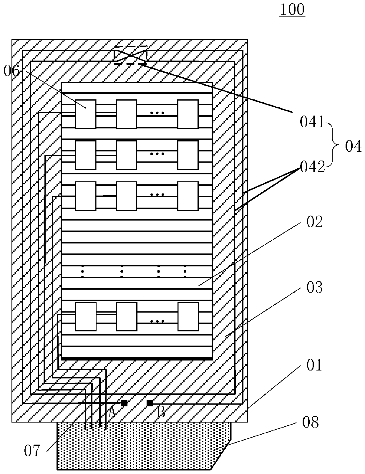
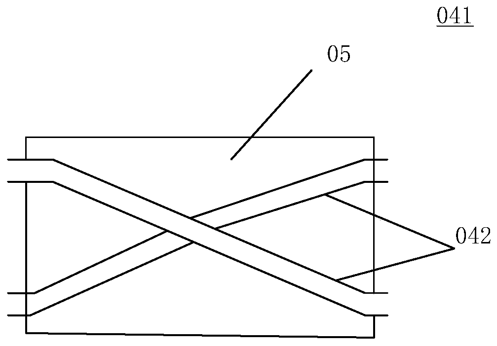
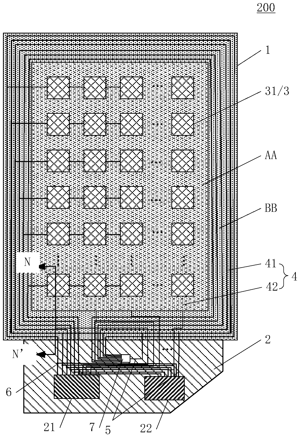
The invention discloses a touch device and a touch display device thereof. The touch device comprises a substrate and a circuit board; the substrate comprises a display area and a non-display area surrounding the display area, the first touch control electrode wires are electrically connected with the touch control driving circuit, the second touch control electrode wires are electrically connected with the touch control driving circuit, and at least one first touch control electrode wire surrounding the non-display area is electrically connected with the near field communication circuit; thesubstrate further comprises an antenna, the antenna surrounds the non-display area, and the antenna is electrically connected with the near-field communication circuit; and the antenna is electricallyconnected with at least one first touch electrode wire surrounding the non-display area, so that the same near-field communication signal is transmitted between the antenna and the first touch electrode wire. According to the touch device and the touch display device thereof disclosed by the invention, an NFC antenna function can be added while a touch function is realized; the NFC antenna is produced without occupying extra procedures, and meanwhile, part of the touch electrode wires are multiplexed into the NFC antenna, so that the NFC antenna does not occupy an extra frame area, and implementation of a narrow frame is facilitated.

Description

technical field [0001] The present invention relates to the field of display technology, and more particularly, to a touch device and a touch display device thereof. Background technique [0002] NFC (Near Field Communication), that is, near field communication technology, has the characteristics of short transmission distance, low energy consumption, and the signal is not easy to be interfered. It is considered suitable for application in smart payment and smart wearable devices; [0003] In the existing products, the NFC antenna is usually an independent external circuit board, which is assembled on the casing of the whole machine, which will incur additional costs, and at the same time, there will be problems of interface wear and signal deterioration, and it will also occupy the space of the whole machine. The structural design of the whole machine brings certain restrictions, such as the need to reserve a card swiping area or the back of the card must be used, which is ...

Claims


Application Information

Patent Timeline
Patent Type & Authority Applications(China)
IPC IPC(8): G06F3/041
CPCG06F3/0416
Inventor 马太昇章玲玲周九斌
Owner SHANGHAI TIANMA MICRO ELECTRONICS CO LTD
Learn More