Push-pull type self-locking connector

A connector, push-pull technology, applied in the direction of connection, two-part connection device, parts of connection device, etc., can solve the problem of unreliable locking of quick-plug connector

Inactive Publication Date: 2020-04-21
昆山先特电子科技有限公司
View PDF3 Cites 6 Cited by
  • Summary
  • Abstract
  • Description
  • Claims
  • Application Information

AI Technical Summary

Problems solved by technology

[0004] The invention provides a push-pull self-locking connector, the purpose of which is to solve the problem of unreliable locking after the existing quick-plug connector is plugged in

Method used


Image

  • Push-pull type self-locking connector
  • Push-pull type self-locking connector
  • Push-pull type self-locking connector

Examples


Embodiment

[0022] Example: a push-pull self-locking connector

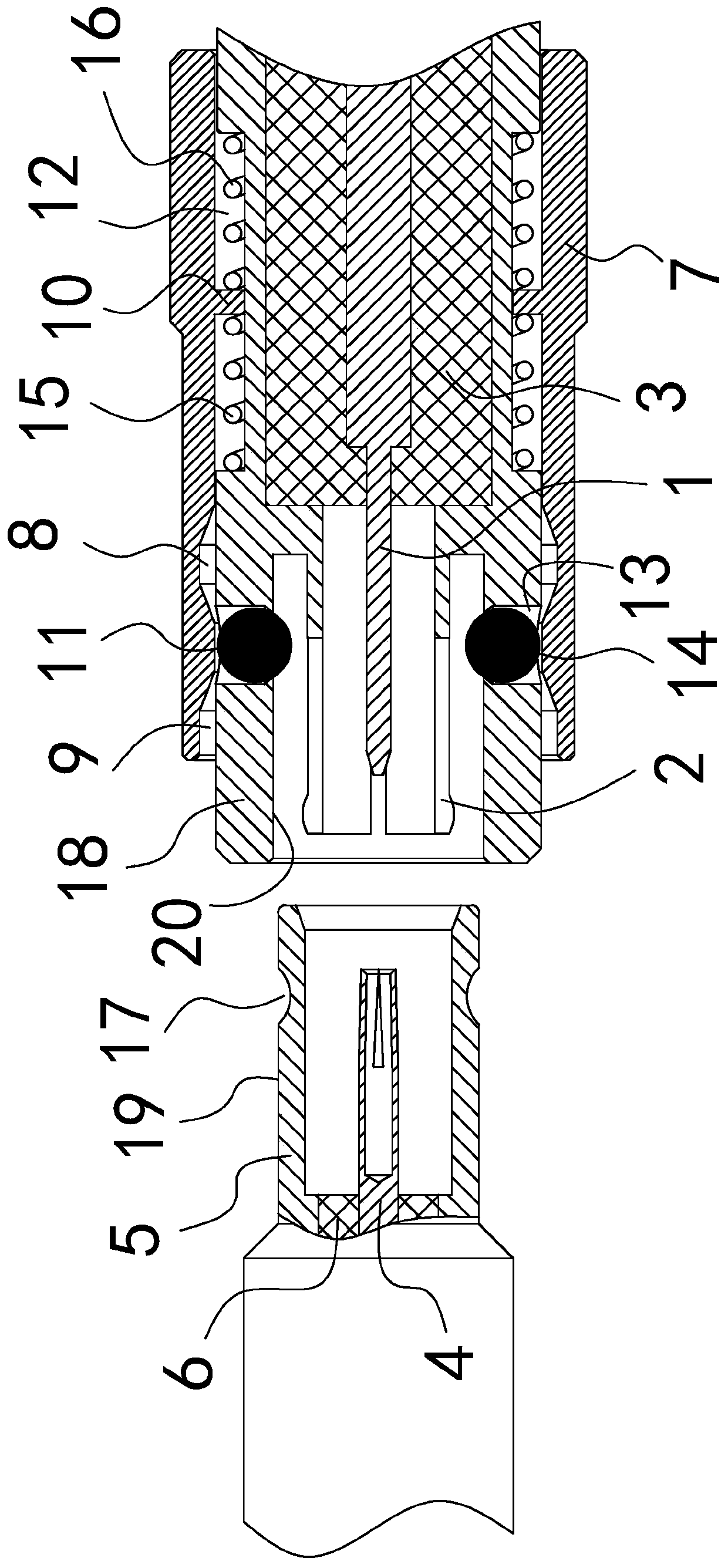
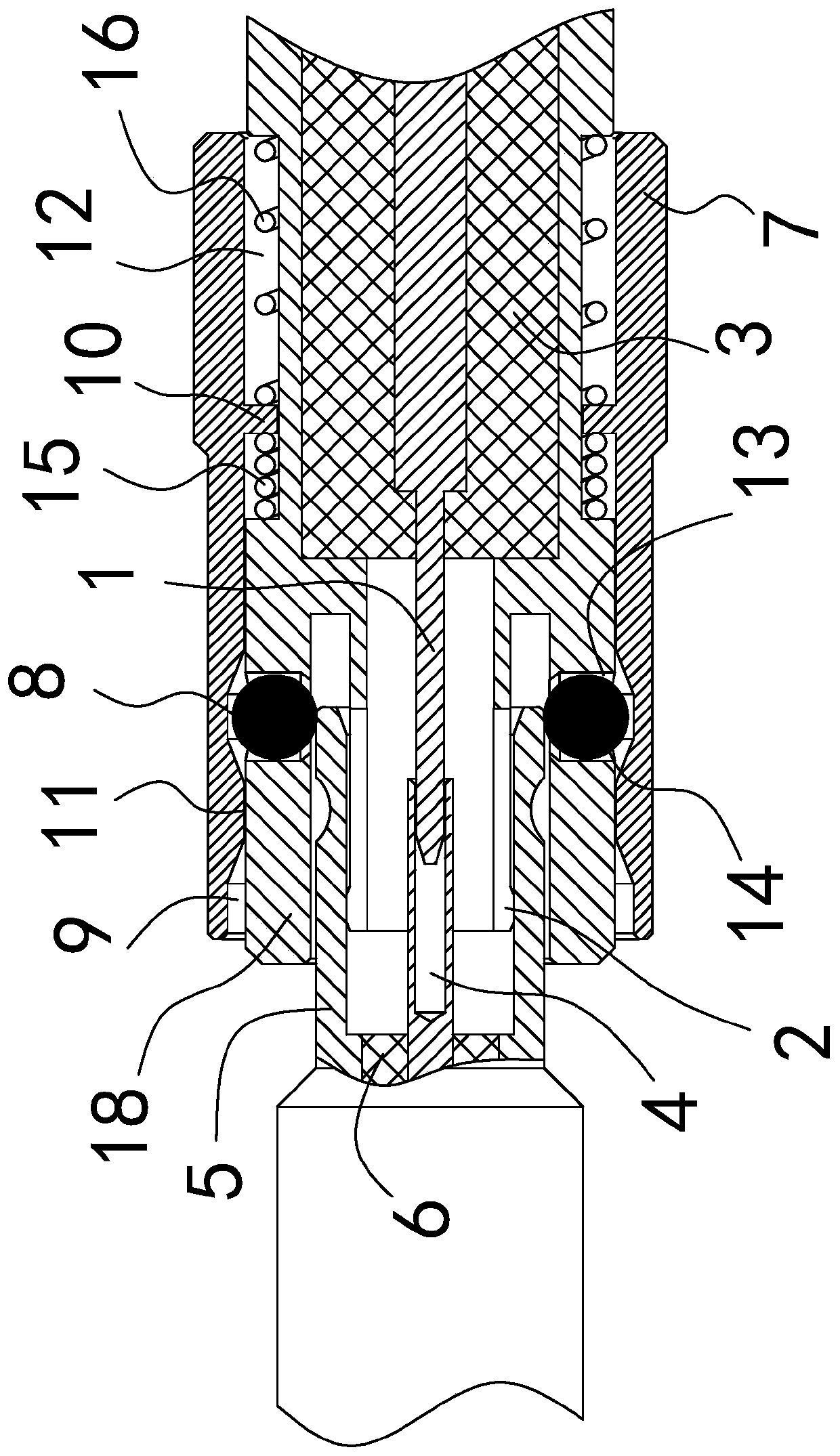
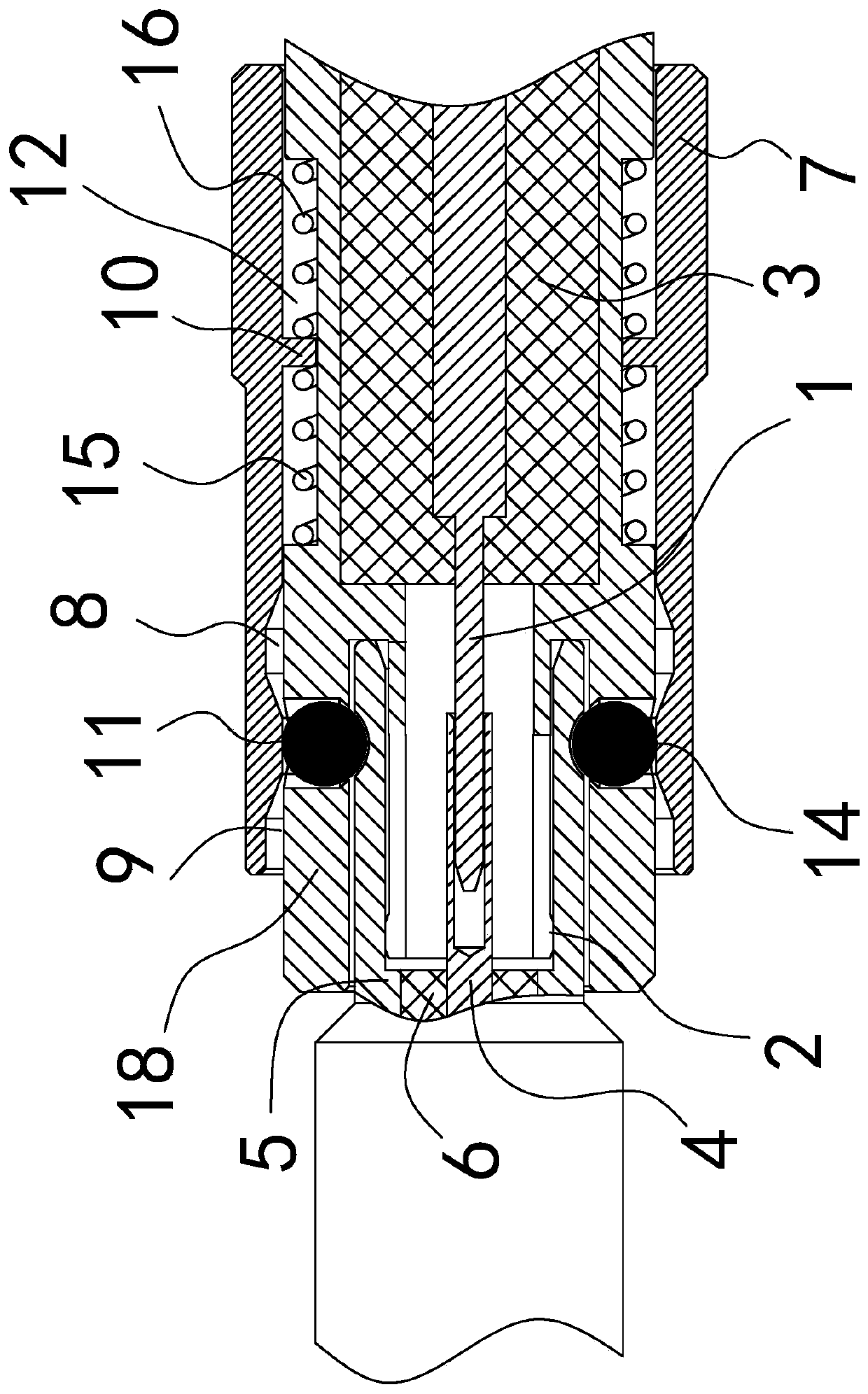
[0023] Such as figure 1 As shown, the connector consists of male and female.

[0024] The male head is composed of a male head inner conductor 1, a male head outer conductor 2, a male head insulator 3, a lock sleeve 7, a lock ball 14, a first spring 15 and a second spring 16 (see figure 1 right half). Wherein, the male insulator 3 is located between the male inner conductor 1 and the male outer conductor 2 for supporting and isolating the male inner conductor 1 and the male outer conductor 2, and the male insulator 3 is an electrical insulating medium. The male inner conductor 1 is a pin, which is used to intermate with the female socket to form a connection. The mating end surface of the male outer conductor 2 is provided with a slotted structure for fully contacting with the female outer conductor 5 to form an electrical connection. The outer conductor 2 of the male head is provided with a jacket 18 (see figure 1 ), t...


PUM


Abstract

The invention discloses a push-pull type self-locking connector. The connector consists of a male head and a female head, wherein one of the male head and the female head is used as a first end of theconnector; and the other one is used as a second end of the connector. An outer sleeve is arranged at the first end. A lock sleeve slidably sleeves an outer side of the outer sleeve. A first lock retreating groove, a locking point and a second lock retreating groove are sequentially arranged in an inner wall of the lock sleeve along an axial direction, a side hole is arranged in an outer wall ofthe outer sleeve, a lock ball is arranged in the side hole, a spring acting in the axial direction is arranged between the outer sleeve and the lock sleeve, and when a spring is located at a balance position in an assembling state, the locking point right faces the side hole. An outer cylindrical surface is arranged at the second end, and an annular groove is arranged in an outer cylindrical surface in a circumferential direction and corresponds to the lock ball. Quick insertion and self-locking of the connector are realized through push-pull action of the lock sleeve, the connector is in a locked state during self-locking, reliability is very high, and the connector cannot be pulled out for unlocking in a pulled state if a pulling force towards an outer end is not actively applied to thelock sleeve.

Description

technical field [0001] The invention belongs to the field of electrical connectors, in particular to a push-pull self-locking connector. Background technique [0002] In radio frequency connection construction, radio frequency connectors are usually used to complete. This type of connector generally consists of a male and a female. During the construction, after the male head and the female head are respectively connected to the cable, the radio frequency connection task can be completed as long as the plug-in connection is made. In order to save labor, RF connectors are required to have quick insertion capabilities. In order to meet the reliability of the connection, the RF connector is required to have a certain locking capability. In the prior art, there are many kinds of radio frequency connectors with quick insertion and locking capabilities, among which, in terms of locking capabilities, most of them are structural forms in which a plurality of shrapnels are formed ...

Claims


Application Information

Patent Timeline
Patent Type & Authority Applications(China)
IPC IPC(8): H01R13/627H01R24/00
CPCH01R13/6276H01R24/00
Inventor 杨胜权
Owner 昆山先特电子科技有限公司
Why Eureka
Try Eureka