
Feeding mechanism

A technology of feeding mechanism and feeding machine, which is applied in the direction of conveyor, conveyor objects, loading/unloading, etc., can solve the problem of large space occupation and so on.

Inactive Publication Date: 2020-04-24
ZHUHAI GREE INTELLIGENT EQUIP CO LTD +1
View PDF7 Cites 6 Cited by
  • Summary
  • Abstract
  • Description
  • Claims
  • Application Information

AI Technical Summary

Problems solved by technology

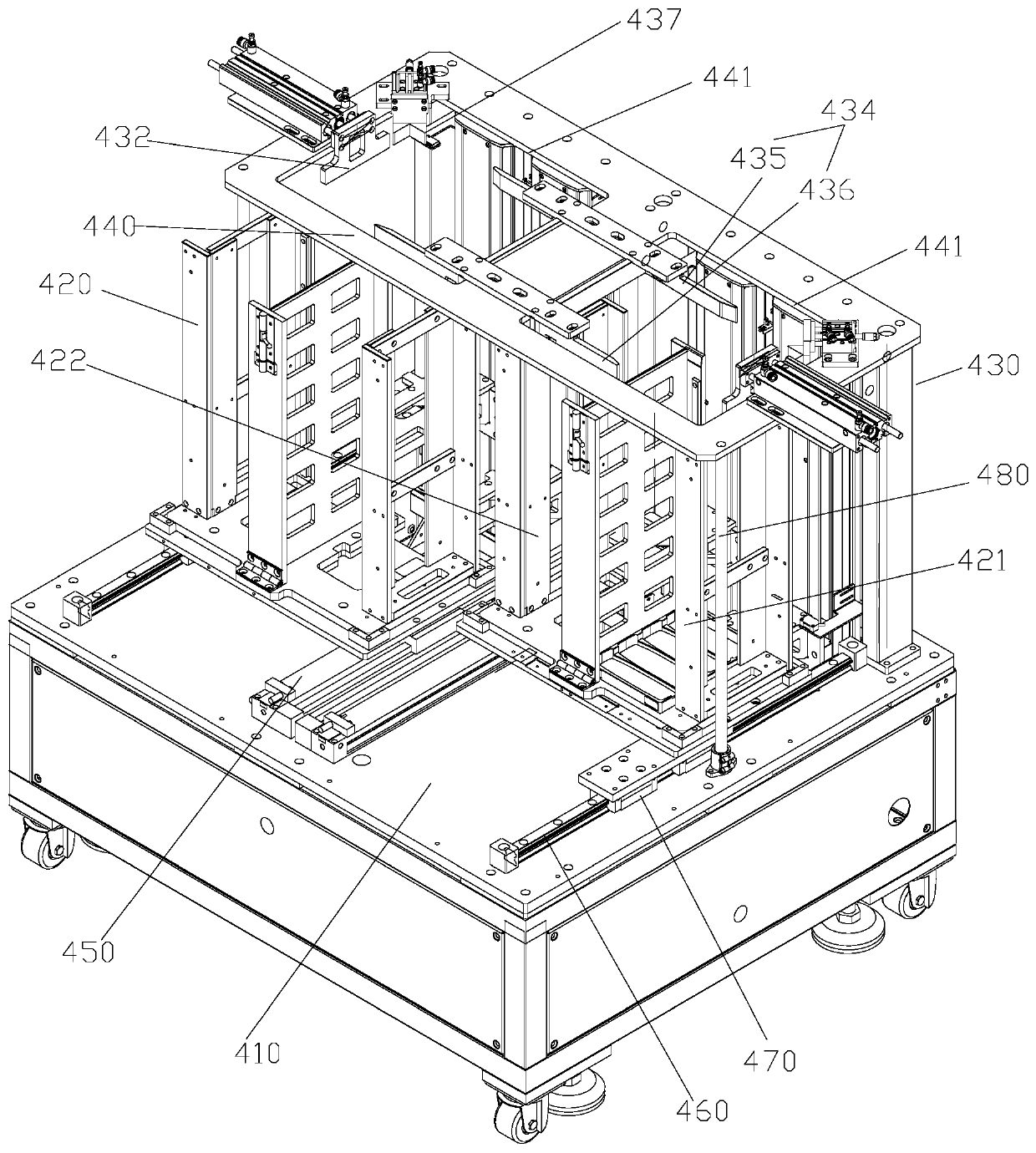
[0004] The main purpose of the present invention is to provide a feeding mechanism to solve the problem that the feeding mechanism in the prior art occupies a large space

Method used


Image

  • Feeding mechanism
  • Feeding mechanism
  • Feeding mechanism

Examples


Embodiment Construction

[0024] It should be noted that, in the case of no conflict, the embodiments in the present application and the features in the embodiments can be combined with each other. The present invention will be described in detail below with reference to the accompanying drawings and examples.

[0025] It should be pointed out that the following detailed description is exemplary and intended to provide further explanation to the present application. Unless defined otherwise, all technical and scientific terms used herein have the same meaning as commonly understood by one of ordinary skill in the art to which this application belongs.

[0026] It should be noted that the terminology used here is only for describing specific implementations, and is not intended to limit the exemplary implementations according to the present application. As used herein, unless the context clearly dictates otherwise, the singular is intended to include the plural, and it should also be understood that wh...


PUM


Abstract

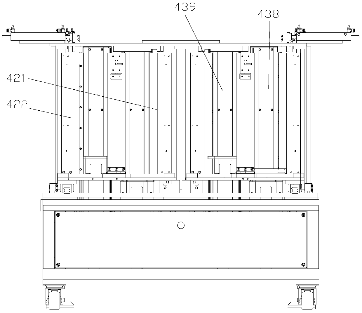
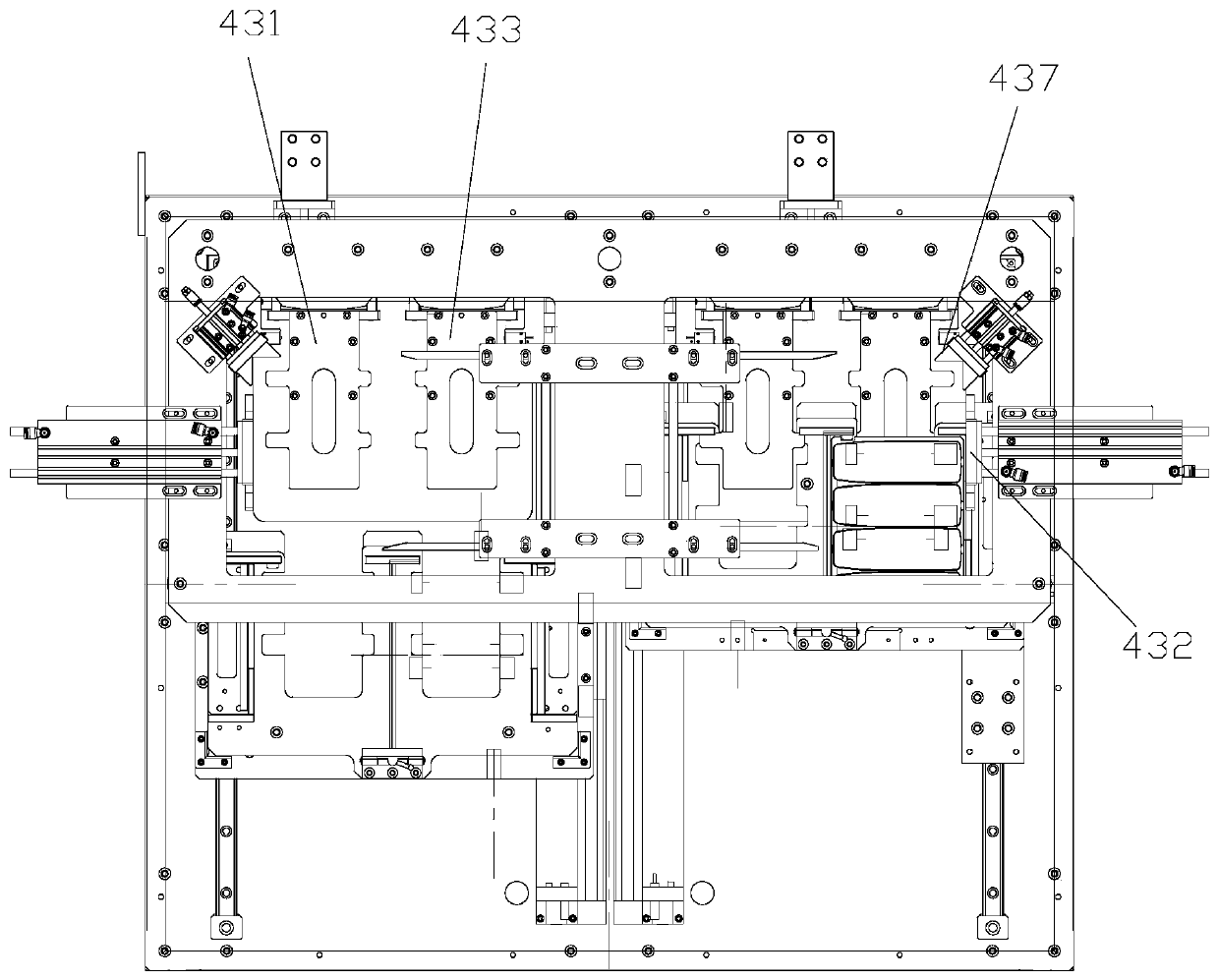
The invention provides a feeding mechanism. The feeding mechanism comprises a feeding machine frame, a stock bin and a feeding assembly; the stock bin is provided with a first storage part and a second storage part, wherein the first storage part is used for storing trays containing materials, and the second storage part is used for storing empty trays completing feeding of the materials; the stock bin is movably arranged relative to the feeding machine frame and has a first position and a second position, and therefore the trays containing the materials can be supplemented into the first storage part when the stock bin is located at the first position, and the stock bin can be moved to the second position for feeding after the materials are supplemented into the first storage part; and the feeding assembly is arranged on the feeding machine frame and used for moving the empty trays completing feeding in the first storage part into the second storage part. By means of the feeding mechanism, the problem that a feeding mechanism is large in occupied space in the prior art can be solved.

Description

technical field [0001] The invention relates to the field of remote control assembly equipment, in particular to a feeding mechanism. Background technique [0002] At present, the traditional cover feeding mechanism mostly adopts the rotary table type feeding mechanism, which is reliable in feeding. [0003] However, the above-mentioned feeding mechanism takes up a lot of space, the cost of the mechanism is also high, and the feeding capacity at one time is limited. Contents of the invention [0004] The main purpose of the present invention is to provide a feeding mechanism to solve the problem that the feeding mechanism in the prior art occupies a large space. [0005] In order to achieve the above object, the present invention provides a feeding mechanism, including: a feeding frame; a silo, the silo has a first storage part and a second storage part, and the first storage part is used to store trays containing materials , the second storage part is used to store the ...

Claims


Application Information

Patent Timeline
Patent Type & Authority Applications(China)
IPC IPC(8): B65G65/32B65G47/82B65G47/90B23P19/00
CPCB23P19/001B65G47/82B65G47/90B65G65/32B65G2201/0258
Inventor 唐小勇黄冀发刘其剑彭永红胡伟涛王欣
Owner ZHUHAI GREE INTELLIGENT EQUIP CO LTD
Learn More