Unwinding and cloth storing mechanism of laminating machine and use method thereof

A technology of laminating machine and cloth storage, which is applied in the direction of winding strips, thin material handling, transportation and packaging, etc., can solve the problems of reduced peeling strength of products, large impact force, and failure to change rolls, etc.

Pending Publication Date: 2020-04-24
常州市永明机械制造有限公司
View PDF0 Cites 2 Cited by
  • Summary
  • Abstract
  • Description
  • Claims
  • Application Information

AI Technical Summary

Problems solved by technology

Because the base cloth of the waiting station that is attached to it is stationary, the faster the base cloth of the working station travels, the greater the relative speed, and the greater the impact force will be. The splice is torn, thereby failing to change the roll
However, the problem caused by speed reduction is that the peel strength of the product will be reduced, and the thickness of the coating film will also change with the change of speed, resulting in fluctuations in product quality.
The best solution is to be able to change rolls without slowing down, and the compounding speed of the current equipment is getting faster and faster, and the mainstream models have reached a speed of more than 200m / min. , to achieve roll change without slowing down, the impact force is too large, it is difficult to achieve

Method used


Image

  • Unwinding and cloth storing mechanism of laminating machine and use method thereof

Examples


Embodiment Construction

[0025] The present invention is described in further detail now in conjunction with accompanying drawing. These drawings are all simplified schematic diagrams, which only illustrate the basic structure of the present invention in a schematic manner, so they only show the configurations related to the present invention.

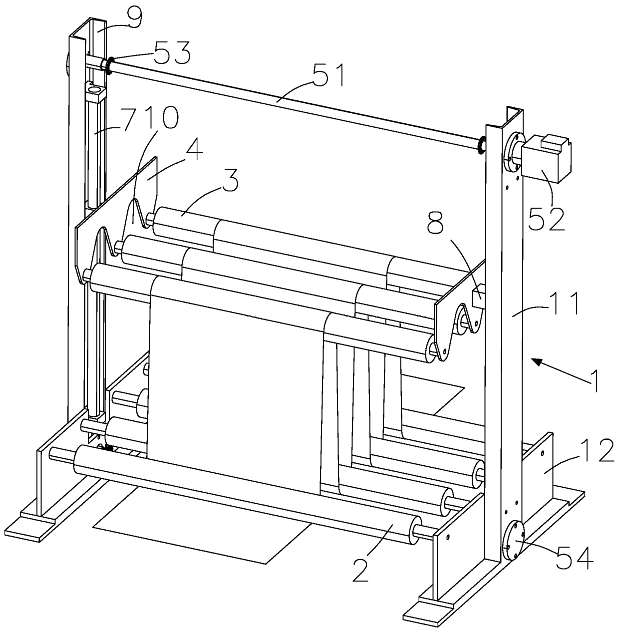
[0026] Such as figure 1 As shown, the present invention is an unwinding and storing cloth mechanism of a laminating machine, including a frame 1, and the frame 1 includes two vertical and symmetrically arranged supports 11, and a base 12 arranged at the bottom of the supports 11 and used to support the supports 11 ; The fixed wheel roller 2, a plurality of fixed wheel rollers 2 are horizontally rotated and arranged between the two bottom plates 12; the moving wheel roller 3, a plurality of moving wheel rollers 3 are arranged horizontally, and each moving wheel roller 3 is located in the gap between two fixed wheel rollers 2 directly above; lifting plate 4, a ...


PUM


Abstract

The invention relates to an unwinding and cloth storing mechanism of a laminating machine. The unwinding and cloth storing mechanism comprises a rack, fixed wheel rollers, movable wheel rollers, lifting plates, a driving mechanism and base cloth, wherein the rack comprises two supports which are vertically and symmetrically arranged and bases which are arranged at the bottoms of the supports and used for supporting the supports; the plurality of fixed wheel rollers are horizontally and rotationally arranged between two bottom plates; the plurality of movable wheel rollers are horizontally arranged, and each movable wheel roller is located over the gap between every two fixed wheel rollers; the two ends of the plurality of driving wheel rollers are rotationally arranged on the lifting plates correspondingly; the driving mechanism drives the lifting plates to ascend and descend in the height direction of the supports; and the base cloth passes through the fixed wheel rollers on the outersides of the bases, is sequentially wound on the movable wheel rollers and the fixed wheel rollers, and is guided out through the fixed wheel rollers on the other sides of the bases. According to theunwinding and cloth storing mechanism, the base cloth is sequentially wound on the movable wheel rollers and the fixed wheel rollers, the movable wheel rollers are driven by the lifting plates to ascend, cloth storage of the base cloth is achieved, the movable wheel rollers are driven by the lifting plates to descend, unwinding of the base cloth is achieved, in the process, the linear speed of anunwinding position is smaller than that of a composite position, and reel changing under the condition that a winding machine does not decelerate is achieved.

Description

technical field [0001] This patent relates to a cloth storage mechanism, in particular to a cloth unwinding and storage mechanism for a laminating machine. Background technique [0002] In the normal lamination process production, it is necessary to bond the base cloth of the working station and the preparation station with double-sided adhesive tape without stopping the machine, and pass through a pair of pressing rollers to make it firmly bonded to achieve non-stop Changing rolls, usually this process needs to be realized by reducing the speed. Because the base cloth of the waiting station that is attached to it is stationary, the faster the base cloth of the working station travels, the greater the relative speed, and the greater the impact force will be. The splice is torn, making the roll change fail. However, the problem caused by speed reduction is that the peel strength of the product will be reduced, and the thickness of the coating film will also change with the ...

Claims


Application Information

Patent Timeline
Patent Type & Authority Applications(China)
IPC IPC(8): B65H20/34B65H19/12
CPCB65H19/12B65H20/34
Inventor 何敏
Owner 常州市永明机械制造有限公司
Why Eureka
Try Eureka