
Mechanical heavy-load self-adaptive automatic speed changing assembly

An automatic shifting and self-adaptive technology, applied in mechanical equipment, automatic clutches, transmissions, etc., can solve the problems of inability to achieve capacity recovery and storage, increase maintenance and replacement costs, and inability to transmit wheel torque, and achieve strong climbing and performance. Heavy load capacity, increase the range of efficient operation, and increase the effect of cruising range

Active Publication Date: 2020-04-24
SOUTHWEST UNIVERSITY
View PDF6 Cites 4 Cited by
  • Summary
  • Abstract
  • Description
  • Claims
  • Application Information

AI Technical Summary

Problems solved by technology

[0003] Due to the limitations of its transmission structure, the existing electric vehicles are completely controlled by the driver based on experience when the driving resistance cannot be accurately known during driving. The actual driving conditions do not match, causing the motor to stall
Especially when the vehicle is under low-speed and heavy-load conditions such as starting, climbing, and headwind, the motor often needs to work at low efficiency, low speed, and high torque, which is likely to cause accidental damage to the motor and increase maintenance and replacement costs. directly affect the battery life
For models with high economic requirements such as electric logistics vehicles, the traditional variable speed transmission structure obviously cannot better meet their use requirements
Moreover, when the electric vehicle is sliding by inertia, due to the structural design problem of the existing automatic transmission, the transmission cannot transmit the torque of the wheel to the motor, so that the capacity recovery and storage cannot be realized, resulting in unsatisfactory cruising range

Method used


Image

  • Mechanical heavy-load self-adaptive automatic speed changing assembly
  • Mechanical heavy-load self-adaptive automatic speed changing assembly
  • Mechanical heavy-load self-adaptive automatic speed changing assembly

Examples


Embodiment Construction

[0038] The present invention will be further described below in conjunction with embodiment and accompanying drawing.

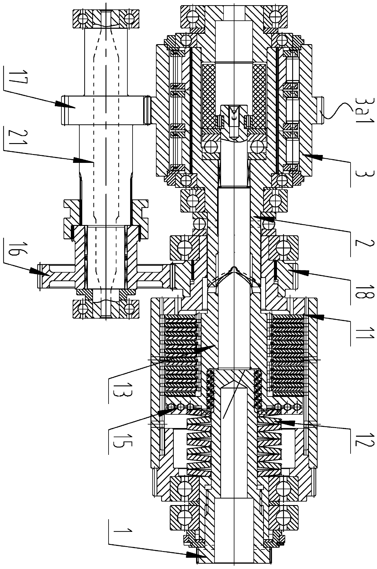
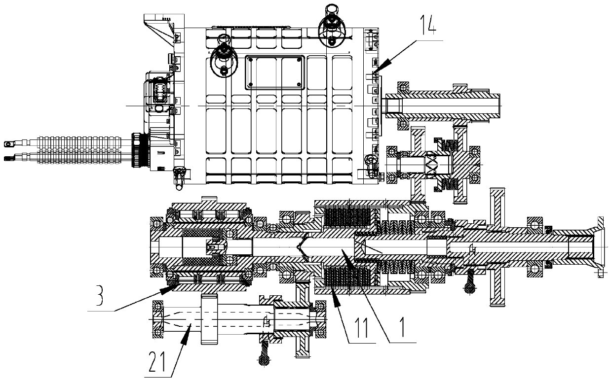
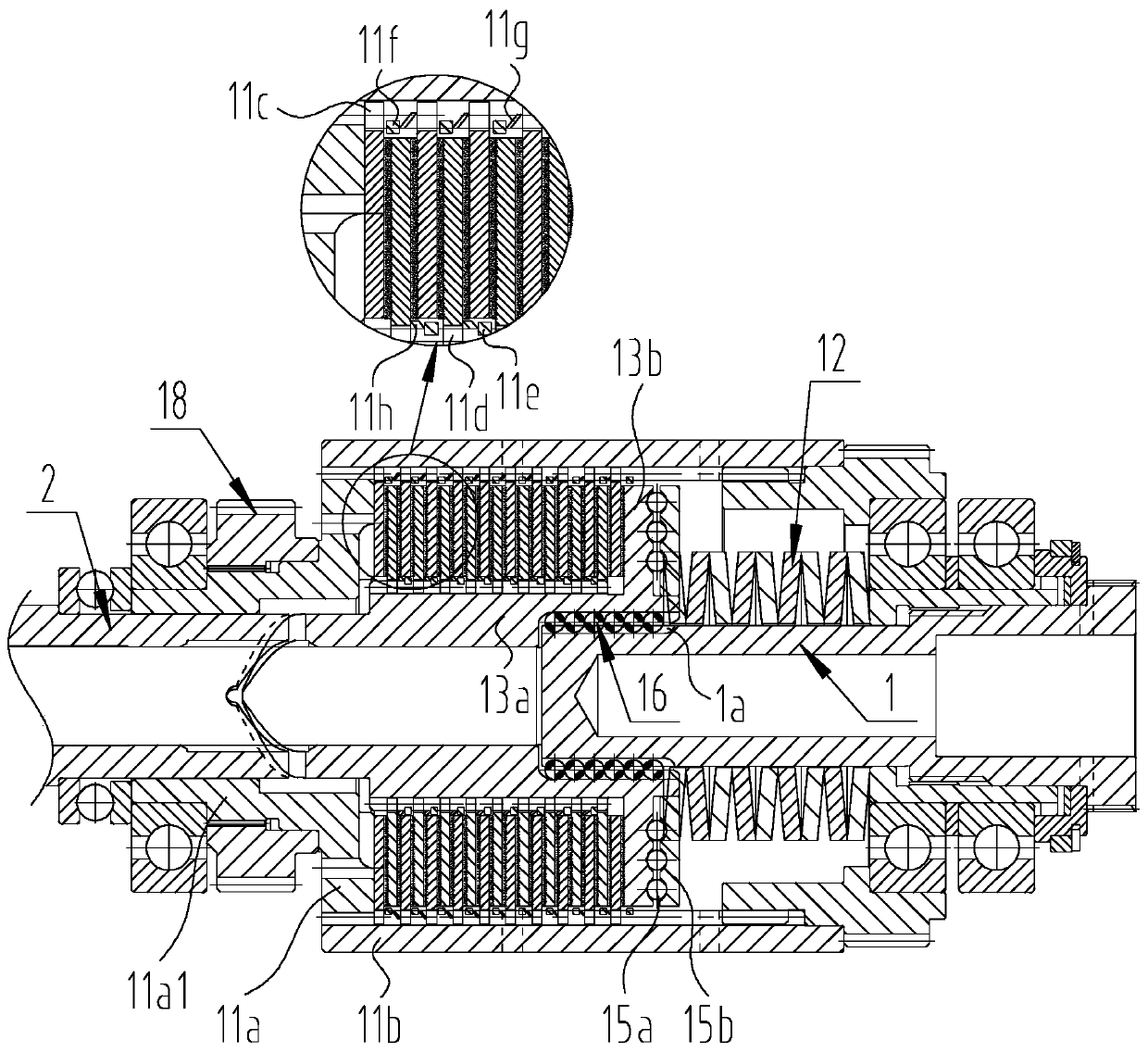
[0039] like Figure 1-Figure 4 As shown, a mechanical heavy-duty adaptive automatic transmission assembly includes a high-speed transmission mechanism, a low-speed transmission mechanism and a main shaft 1 for outputting power.

[0040] The high-speed gear transmission mechanism includes a friction clutch 11 and an elastic element group 12 for applying pretightening force to the friction clutch 11. The friction clutch 11 is sleeved on the main shaft 1 through an inner spiral raceway sleeve 13. A spiral transmission pair is formed between the spiral raceway sleeve 13 and the main shaft 1 , so that the inner spiral raceway sleeve 13 can slide axially along the main shaft 1 .

[0041] The low-speed gear transmission mechanism includes a multi-row combined overrunning clutch 3 set on the main shaft 1 through an inner wheel sleeve 2 and a countershaft transmissio...


PUM


Abstract

The invention discloses a mechanical heavy-load self-adaptive automatic speed changing assembly, comprising a high-speed gear transmission mechanism, a low-speed gear transmission mechanism and a mainshaft used for outputting power. By adopting such a technical scheme, the actual driving working condition and the motor working condition of a purely-electric vehicle can be matched in a self-adaptive mode, the purely-electric vehicle has high climbing capacity and heavy load capacity, a motor is located on an efficient platform all the time, the efficiency of the motor under the climbing and heavy load conditions is greatly improved, and the energy consumption of the motor is reduced; gear-shifting speed changing can be automatically carried out along with running resistance changes in a self-adaptive mode under the condition that driving force is not cut off and gear shifting smoothness is achieved, the efficient running interval of the motor is greatly increased, the motor can be usedin mountainous areas, hills and heavy load conditions, the load change of the motor or an engine is gentle, and the purely-electric vehicle runs stably and is high in safety; moreover, when the electric vehicle slides in an inertia mode, energy can be recycled and stored, and therefore, endurance mileage is increased.

Description

technical field [0001] The invention relates to the technical field of mechanical transmissions, in particular to a mechanical heavy-duty self-adaptive automatic transmission assembly. Background technique [0002] With the increasingly stringent environmental protection regulations, it is the general trend that new energy vehicles represented by pure electric vehicles, motorcycles and tricycles will replace traditional fuel vehicles. [0003] Due to the limitations of its transmission structure, the existing electric vehicles are completely controlled by the driver based on experience when the driving resistance cannot be accurately known during driving. The actual driving conditions do not match, causing the motor to stall. Especially when the vehicle is under low-speed and heavy-load conditions such as starting, climbing, and headwind, the motor often needs to work at low efficiency, low speed, and high torque, which is likely to cause accidental damage to the motor and ...

Claims


Application Information

Patent Timeline
Patent Type & Authority Applications(China)
IPC IPC(8): F16D43/21F16D47/04F16H3/10F16H63/30
CPCF16H3/10F16H63/30F16D47/04F16D43/216
Inventor 薛荣生张引航陈俊杰王靖陈同浩谭志康邓天仪邓云帆梁品权颜昌权
Owner SOUTHWEST UNIVERSITY
Learn More