
Stator core and motor

A stator core and iron core technology, applied in the prevention/reduction of eddy current loss in the winding head, magnetic circuit shape/style/structure, electrical components, etc., can solve problems such as magnetic flux loss, and achieve the goal of reducing magnetic flux loss Effect

Pending Publication Date: 2020-04-24
NIDEC CORP
View PDF10 Cites 0 Cited by
  • Summary
  • Abstract
  • Description
  • Claims
  • Application Information

AI Technical Summary

Problems solved by technology

Therefore, there is a problem that magnetic flux loss occurs

Method used


Image

  • Stator core and motor
  • Stator core and motor
  • Stator core and motor

Examples


Embodiment Construction

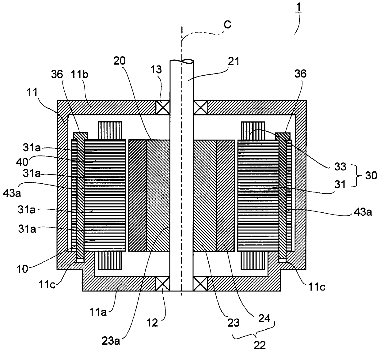
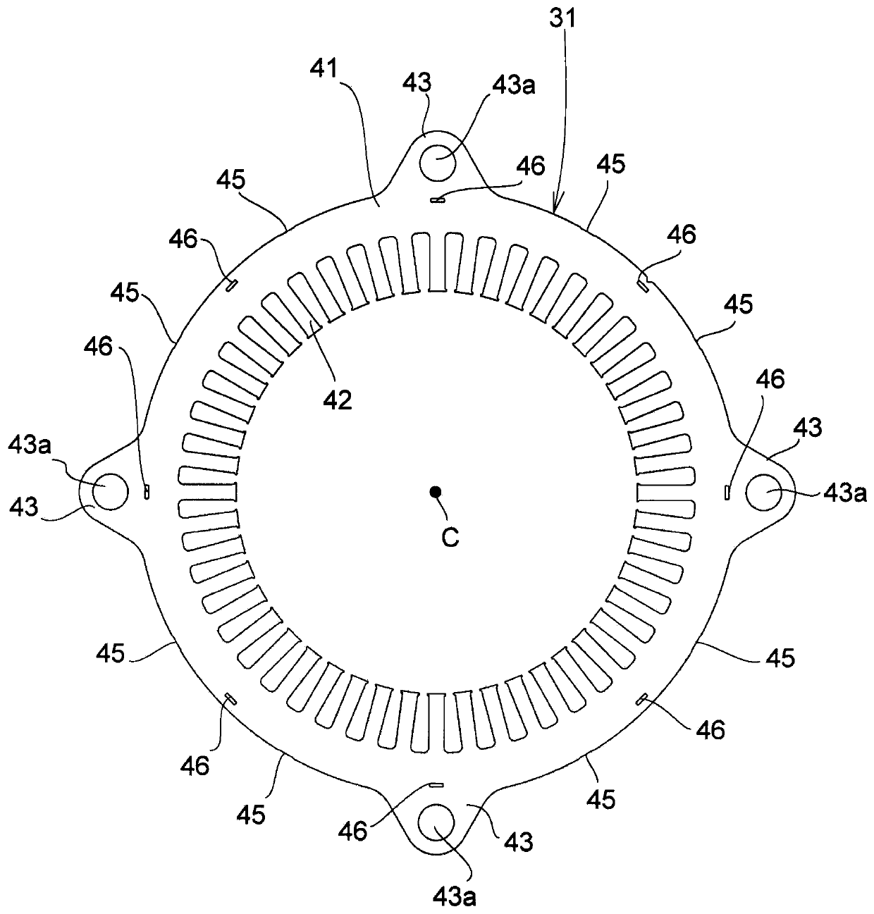
[0015] Hereinafter, exemplary embodiments of the present invention will be described in detail with reference to the drawings. In this specification, the upper side in the central axis direction of the motor is referred to as "upper side", and the lower side is referred to as "lower side". In addition, the up-down direction does not indicate the positional relationship or direction when assembled in an actual device. In addition, the direction parallel or substantially parallel to the central axis is referred to as "axial direction", the radial direction centered on the central axis is simply referred to as "radial direction", and the circumferential direction centered on the central axis is referred to as "circumferential direction". Towards". In addition, in this specification, the shape and positional relationship of each part are demonstrated using the axial direction as an up-down direction, and the top plate part 11b side as an upper direction with respect to the bottom...


PUM


Abstract

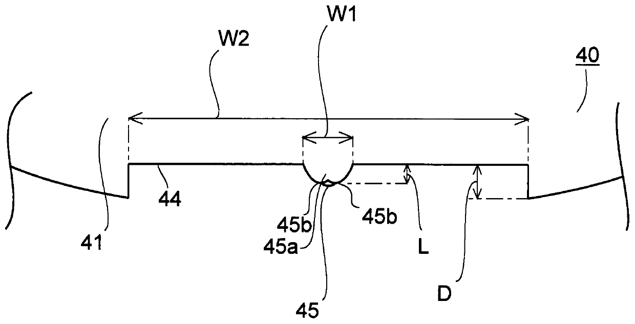
A stator core and a motor are provided. The stator core includes plate-shaped core members laminated to define the stator core. Each core member includes an annular core back portion, and tooth portions that project radially inward from an inner circumferential surface of the core back portion. The core back portion includes at least one recessed portion recessed radially inward from an outer circumferential surface of the core back portion, and at least one welded portion arranged at a corresponding one of the at least one recessed portion to join axially adjacent ones of the core members. The at least one recessed portion is recessed in a radial direction is in a range of about 0.2 mm to about 1.5 mm, both inclusive.

Description

technical field [0001] The invention relates to a stator core and a motor. Background technique [0002] Patent Document 1 discloses a conventional stator core. The stator core (Stator core) disclosed in Patent Document 1 is formed by laminating a plurality of ring-shaped electromagnetic steel sheets. The magnetic steel sheets adjacent to each other in the axial direction are joined by welding to be integrated. Welding is performed using a welded portion provided on the outer peripheral surface of the electrical steel sheet. [0003] The stator core has a plurality of teeth protruding radially inward. A conductive wire is wound around each tooth, and a coil is formed around each tooth. When a driving current flows through the wire, a magnetic field is generated in the coil. At this time, the magnetic flux generated by the coil goes radially outward through the teeth and travels in the circumferential direction on the outer peripheral portion of the stator core. The mag...

Claims


Application Information

Patent Timeline
IPC IPC(8): H02K1/18
CPCH02K1/18H02K2213/03H02K1/16H02K2201/09H02K1/185H02K3/42H02K1/14H02K1/08
Inventor 福永庆介
Owner NIDEC CORP
Learn More