
Reactor

A reactor and iron yoke technology, applied in circuits, transformer/inductor cores, electrical components, etc., can solve the problems of space compression of the winding winding of the reactor, the inability to provide the reactor structure, and the inability to wind the coil.

Pending Publication Date: 2020-11-17
SCHAFFNER EMC SHANGHAI LTD
View PDF0 Cites 0 Cited by
  • Summary
  • Abstract
  • Description
  • Claims
  • Application Information

AI Technical Summary

Problems solved by technology

[0005] If the saturation flux is increased by increasing the contact area between the magnetic powder core and ferrite, limited by the manufacturing process, the part of the magnetic powder core used to increase the contact area with the ferrite cannot be wound around the coil, which will result in a reactor The winding space available for winding the winding in the
[0006] All in all, the existing technology cannot provide a reactor structure that can take into account the overall volume of the reactor, the winding space and the saturation flux

Method used


Image

  • Reactor
  • Reactor
  • Reactor

Examples


Embodiment Construction

[0033] As mentioned in the background art, the prior art cannot provide a reactor structure that can take into account the overall volume of the reactor, the winding space and the saturation magnetic flux.

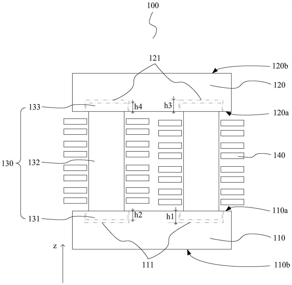
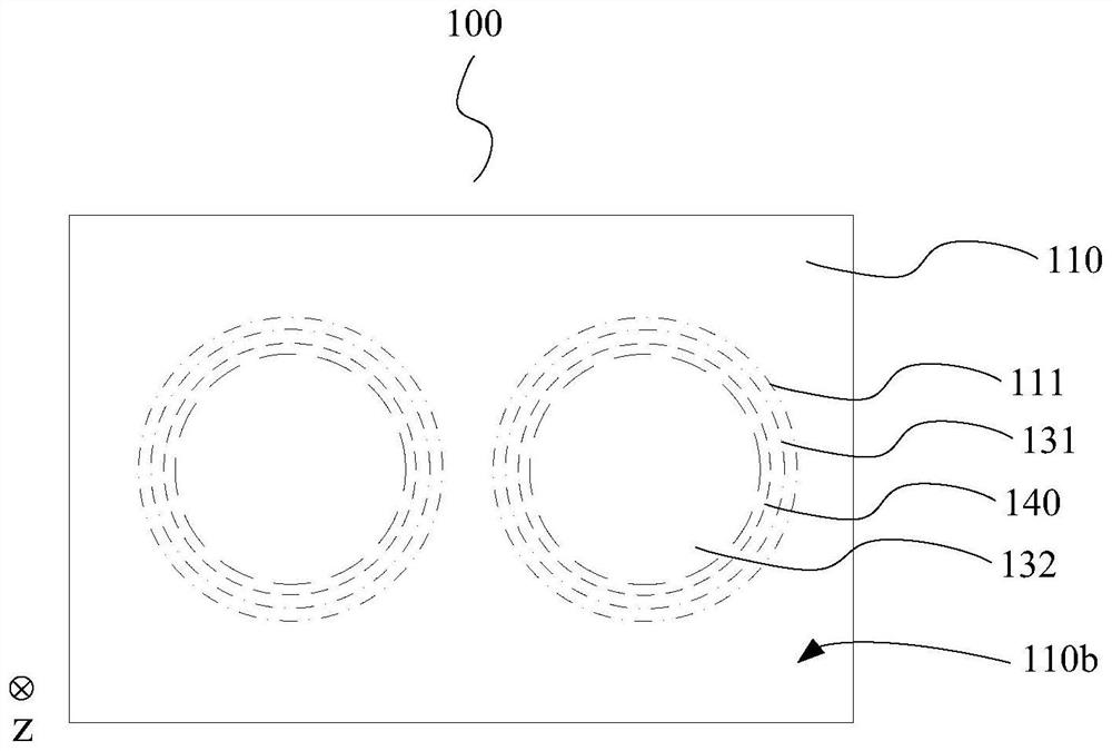
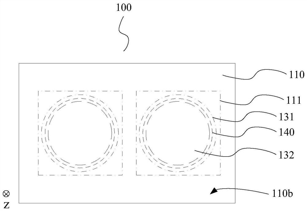
[0034] In order to solve the above technical problems, an embodiment of the present invention provides a reactor, including: a lower iron yoke, the lower iron yoke has a first surface and a second surface opposite to each other, wherein the first surface of the lower iron yoke is opened There is a first groove; an upper iron yoke, the upper iron yoke has an opposite first surface and a second surface, wherein the first surface of the upper iron yoke is provided with a second groove, and the upper iron yoke The first surface is set facing the first surface of the lower iron yoke; the central column located between the lower iron yoke and the upper iron yoke, along the first direction, the central column sequentially includes a first part, a second part and a second part Thr...


PUM


Abstract

A reactor comprises a lower iron yoke, and an upper iron yoke, wherein the first surface of the lower iron yoke is provided with a first groove, the first surface of the upper iron yoke is provided with a second groove, and the first surface of the upper iron yoke faces the first surface of the lower iron yoke; a center pillar which is located between the lower iron yoke and the upper iron yoke and sequentially comprises a first part, a second part and a third part in the first direction; and a coil wound which is around the second part of the center pillar, wherein the first groove is suitable for accommodating the first part of the center pillar, and the second groove is suitable for accommodating the third part of the center pillar; the area of the cross section of the first part of thecenter pillar is larger than that of the cross section of the second part of the center pillar, the area of the cross section of the third part of the center pillar is larger than that of the cross section of the second part of the center pillar, and the cross section is perpendicular to the first direction. Through the scheme provided by the invention, on the premise of not increasing the overall volume of the reactor and not reducing the winding space, the magnetic flux loss is reduced, and the saturated magnetic flux is effectively increased.

Description

technical field [0001] The present invention relates to the technical field of reactors, in particular to a reactor. Background technique [0002] In order to achieve the purpose of reducing loss, size and core weight, existing reactors usually adopt a composite core structure, that is, by using a soft magnetic metal powder core for the coil winding part, and using a ferrite The composite magnetic core is formed by combining the magnetic cores for the yoke portion. [0003] The advantage of the composite magnetic core is that it can overcome the problem of increased core loss when the switching frequency exceeds a certain limit in the power circuit scenario. [0004] Since the yoke of the composite magnetic core is still made of ferrite, and the saturation flux of ferrite is low, although the saturation flux can be increased by increasing the ferrite area, the effect of the improvement is limited and will increase The overall volume of the large reactor. [0005] If the s...

Claims


Application Information

Patent Timeline
IPC IPC(8): H01F27/24H01F27/30
CPCH01F27/24H01F27/306
Inventor 陈全光杨志辉
Owner SCHAFFNER EMC SHANGHAI LTD
Learn More