
A molding die

A molding and mold technology, applied in the field of molds, can solve the problems of material ejection to the outside of the mold, unbalanced mold opening pressure loss, popping noise, etc., so as to improve the sealing effect, improve the product molding rate, and improve the pressure uniformity. Effect

Active Publication Date: 2021-11-05
QINGDAO HISENSE MOLD
View PDF13 Cites 0 Cited by
  • Summary
  • Abstract
  • Description
  • Claims
  • Application Information

AI Technical Summary

Problems solved by technology

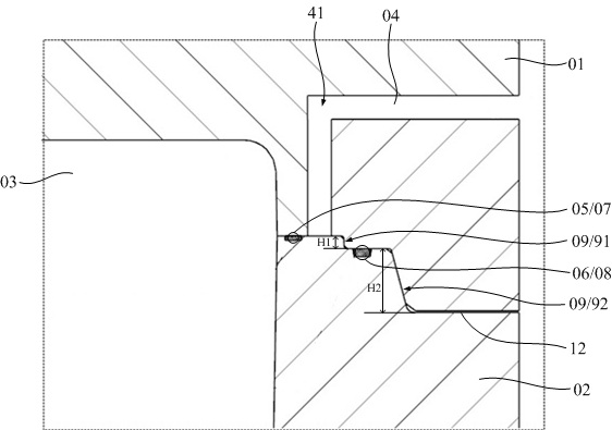
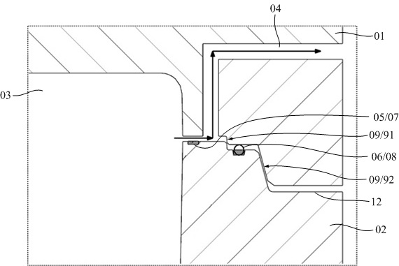
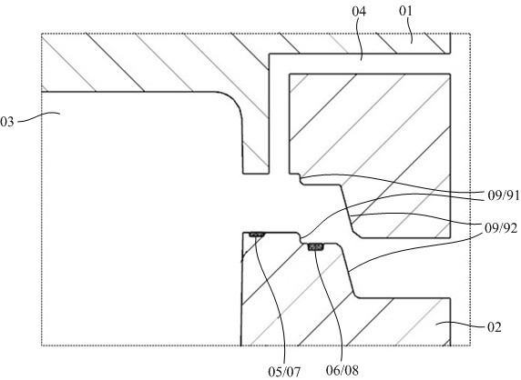
[0005] In order to solve the problems of unbalanced mold opening pressure loss, popping noise, and material ejection to the outside of the mold during the pressure relief process of the compression molding mold in the prior art, the present invention provides a compression molding mold. Double seals are set on the parting surface formed by the contact between the first mold and the second mold to improve the sealing performance; there is an exhaust part connected to the outside atmosphere between the two seals. When the pressure is released, the high-pressure gas in the cavity It is discharged through the sealing part and exhaust part on the inner side to realize slow pressure relief, thereby avoiding the situation of popping and material ejection to the outside of the mold, and at the same time helping to improve the molding rate of the product

Method used


Image

  • A molding die
  • A molding die
  • A molding die

Examples


Embodiment Construction

[0031] The following will clearly and completely describe the technical solutions in the embodiments of the present invention with reference to the accompanying drawings in the embodiments of the present invention. Obviously, the described embodiments are only some, not all, embodiments of the present invention. Based on the embodiments of the present invention, all other embodiments obtained by persons of ordinary skill in the art without making creative efforts belong to the protection scope of the present invention.

[0032] In the description of the present invention, it should be understood that the orientation or positional relationship indicated by the terms "upper", "lower", "inner", "outer" etc. is based on the orientation or positional relationship shown in the drawings, and is only for It is convenient to describe the present invention and simplify the description, but does not indicate or imply that the device or element referred to must have a specific orientation,...


PUM


Abstract

The invention discloses a mold for compression molding, which comprises a first mold and a second mold for enclosing a molding cavity, a parting surface is formed between the two, and a first sealing part and a second sealing part are arranged on the parting surface The first mold or the second mold is provided with an exhaust section, one end of the exhaust section communicates with the parting surface and is located between the first sealing section and the second sealing section, and the other end of the exhaust section is connected to the outside atmosphere. When the mold is in the first mold opening stage, the first sealing part fails, and at this time the position of the second sealing part is still in a sealed state, and the gas in the cavity is discharged to the outside atmosphere through the first sealing part and the exhaust part , the exhaust part guides the high-pressure gas in the cavity to realize slow pressure relief, thereby avoiding the loss of mold opening pressure caused by the gas in the cavity being ejected from the parting surface in a large area at once when the mold is opened Imbalance, popping, seal damage, material ejection to the outside of the mold, etc. help to improve the product molding rate.

Description

technical field [0001] The invention relates to the technical field of molds, in particular to a compression molding mold. Background technique [0002] Compression molding, also known as compression molding or compression molding, is the operation of first putting powdery, granular or fibrous plastics into the mold cavity at the molding temperature, and then closing the mold and pressing it to form and solidify. Compression molding can be used for thermosetting plastics, thermoplastics and rubber materials. Compression molding is widely used in packaging, isolation, filling and other fields. The products produced by compression molding technology have the advantages of light material, good isolation effect, and good impact absorption. [0003] Compression molding includes two parts stages. In the first stage, high temperature and high pressure are used after the mold material is filled, and the material is filled with pressure in the cavity. The material expands under the ...

Claims


Application Information

Patent Timeline
Patent Type & Authority Patents(China)
IPC IPC(8): B29C43/36B29C43/32
CPCB29C43/32B29C43/36B29C43/3607
Inventor 王家昌施一楠张明磊王桂龙赵国群
Owner QINGDAO HISENSE MOLD
Learn More