Roller chain for applying pressure

a technology of roller chain and substrate, applied in the direction of auxillary welding devices, instruments, soldering apparatus, etc., can solve the problems of insufficient overall pressure, less than satisfactory if scaled to accommodate larger images, 810 inch images, etc., to achieve high crushing pressure against the substrate, improve the effect of pressure uniformity and high mechanical toleran

Inactive Publication Date: 2006-01-24
EASTMAN KODAK CO
View PDF13 Cites 0 Cited by
  • Summary
  • Abstract
  • Description
  • Claims
  • Application Information

AI Technical Summary

Benefits of technology

[0012]It is an advantage of the present invention that it is suitable for processing a substrate that is held against a rotatable drum or against a movable flat platen.
[0013]It is an advantage of the present invention that, when used in combination with a rotatable drum, the apparatus of the present invention can be configured both to provide pressure and to provide torque that causes drum rotation at a suitable speed for substrate processing.
[0014]It is an advantage of the present invention that it provides improved pressure uniformity, even where the underlying platen may have some amount of surface irregularity.
[0015]It is a further advantage of the present invention that it provides a scalable solution that can be appropriately sized for handling a range of different substrate sizes.
[0016]It is a further advantage of the apparatus of the present invention that it is capable of providing a high degree of crushing pressure against a substrate. A comparable pressure roller system of conventional design would require that considerable force be maintained between pressure rollers, and that highly accurate mechanical tolerances be maintained throughout pressure application, in order to achieve similarly high levels of crushing pressure in a uniform manner.

Problems solved by technology

However, for some applications, particularly where it is necessary to apply a substantial amount of pressure uniformly onto a substrate surface, such as when processing the Cycolor print media, there are drawbacks to the conventional use of paired rollers.
Thus, for example, the paired roller solution of U.S. Pat. No. 5,208,609 may work adequately with small-format Cycolor images, but be less than satisfactory if scaled to accommodate larger images, such as 8×10 inch images.
Acknowledged among the drawbacks to the use of rollers are problems due to surface imperfections, insufficient overall pressure between rollers, sag, eccentricity about axes of rotation, and non-uniform force distribution across the nip.
However, the slow speed of the oscillating point-contact approach makes this approach commercially unattractive.
Even this solution, however, does not boost throughput speed sufficiently for commercialization.
However, prior art approaches have not yet provided a robust, low cost solution to the problem of applying, onto a sheet of substrate having a range of possible dimensions, sufficient pressure with the needed level of uniformity and with the processing speed needed for imaging applications.

Method used


Image

  • Roller chain for applying pressure
  • Roller chain for applying pressure
  • Roller chain for applying pressure

Examples


Embodiment Construction

[0031]The present description is directed in particular to elements forming part of, or cooperating more directly with, apparatus in accordance with the invention. It is to be understood that elements not specifically shown or described may take various forms well known to those skilled in the art.

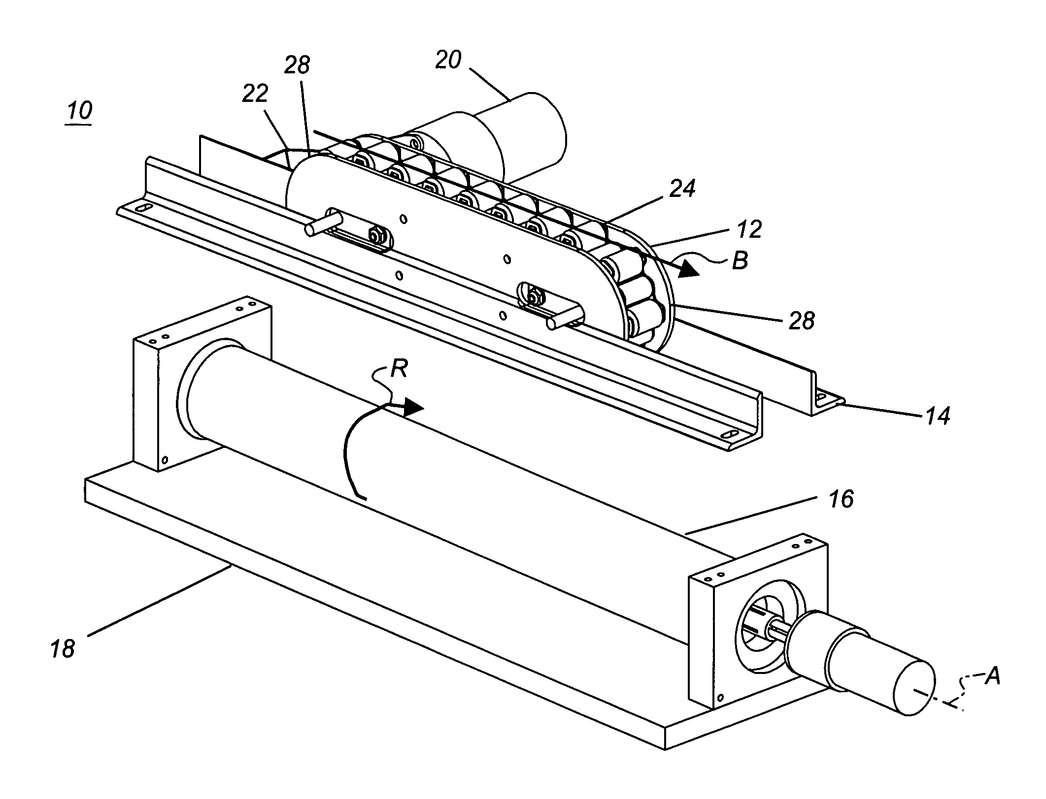
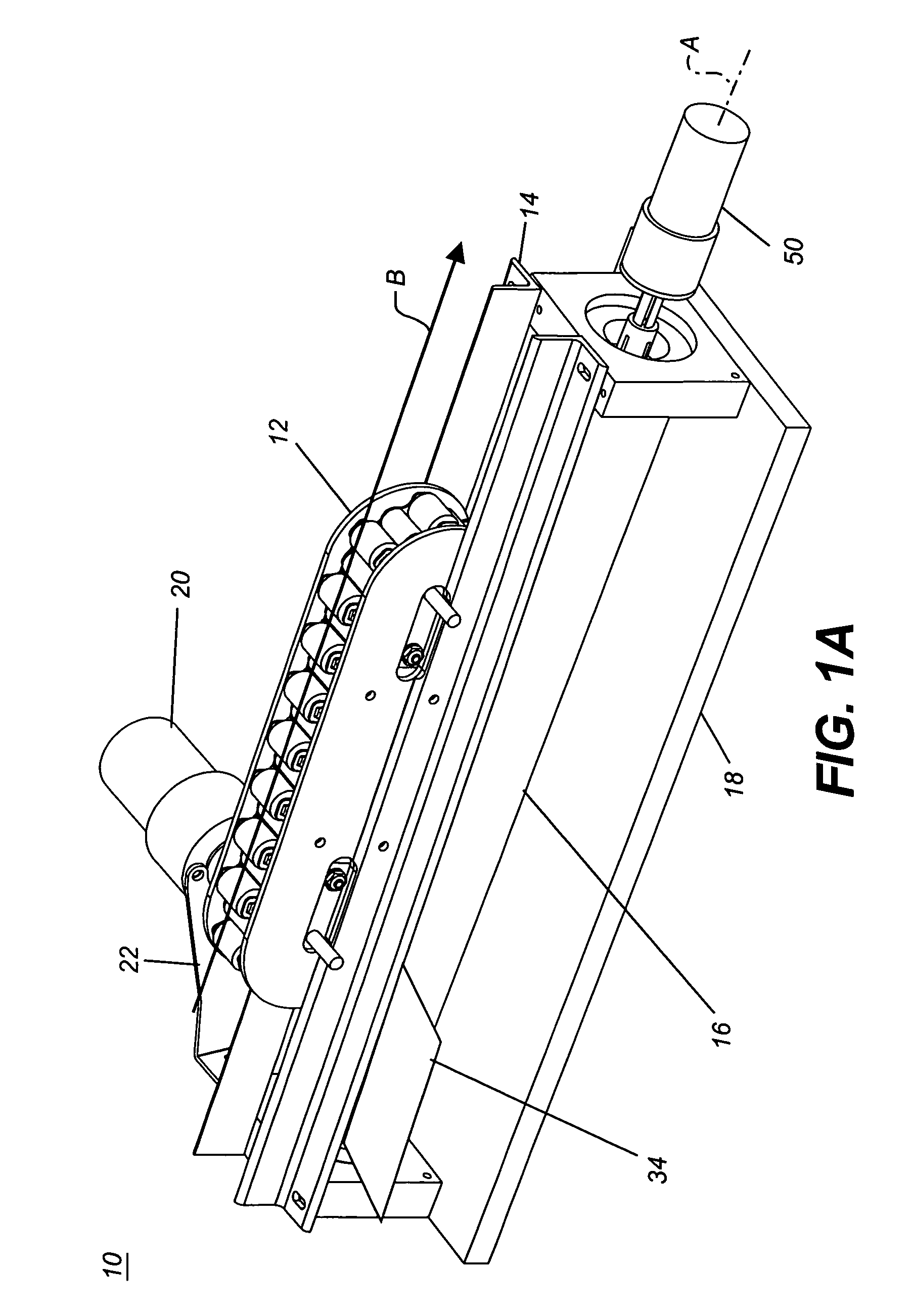
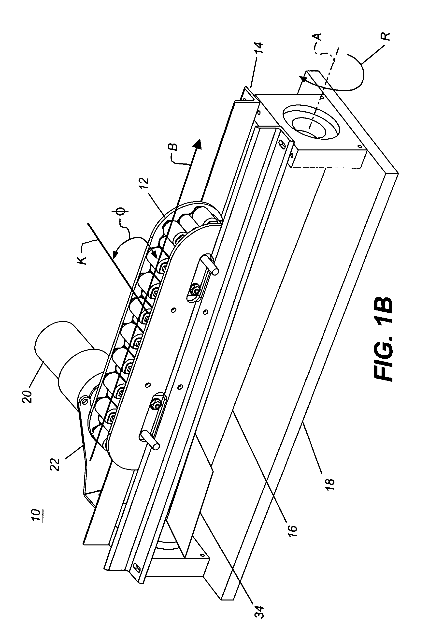
[0032]Referring to FIG. 1a, there is shown a perspective view of a pressure application apparatus 10 according to one embodiment of the present invention. Arranged in a closed loop, a chained roller assembly 12, held by a mounting bracket 14, is pressed against a platen 16. In the configuration of FIG. 1a, platen 16 is a rotatable drum mounted in a base 18 and rotated by a motor 50. However, other types of platen 16 could be employed, including a flat platen, as is described subsequently. In operation, a sheet 34 of substrate may be wrapped about the rotatable drum of base 18 for processing or may simply be fed between chained roller assembly 12 and platen 16. While motor 50 rotates platen...


PUM

PropertyMeasurementUnit
angleaaaaaaaaaa
pressureaaaaaaaaaa
spring forceaaaaaaaaaa

Abstract

An apparatus (10) applies pressure against a platen (16) using a linked series of contact members arranged in a closed loop. A drive apparatus rotates the loop about a support mechanism, thereby imparting movement to the linked series of contact members. The support mechanism is disposed to force a plurality of the moving contact members simultaneously into compressive contact against the platen (16).

Description

FIELD OF THE INVENTION[0001]This invention generally relates to apparatus for applying pressure onto the surface of a substrate and more particularly relates to an apparatus and method for applying pressure by moving a linked series of contact members maintained in compressive contact with a portion of the substrate that is disposed between the contact members and a platen.BACKGROUND OF THE INVENTION[0002]There are a number of imaging applications that require, at some stage in processing, the application of a uniform pressure onto the surface of a substrate. Conventional offset lithographic printing equipment, for example, uses applied pressure for transferring an ink colorant from a printing plate onto the print substrate. Various types of office duplicating equipment, such as xerographic copiers, use pressure from paired rollers for image transfer onto paper or other suitable substrate. Laminators, such as that used with the “KODAK APPROVAL Digital Proofing System”™ available fro...

Claims


Application Information

Patent Timeline
Patent Type & Authority Patents(United States)
IPC IPC(8): B30B5/00B30B5/06G03F7/00
CPCG03F7/0027Y10T156/1741
Inventor BLANDING, DOUGLASS L.
Owner EASTMAN KODAK CO
Why Eureka
Try Eureka