A flow field uniform device designed with large and small blades

A technology of large blades and small blades, applied in the field of flow field control of liquid-filled pipelines, to achieve the effects of strong environmental adaptability, enhanced rectification effect, and compact structure

Inactive Publication Date: 2019-07-19
NO 719 RES INST CHINA SHIPBUILDING IND
View PDF6 Cites 0 Cited by
  • Summary
  • Abstract
  • Description
  • Claims
  • Application Information

AI Technical Summary

Problems solved by technology

[0004] In view of the deficiencies in the prior art, the purpose of the present invention is to provide a flow field uniform device designed with large and small blades, which breaks the original vortex structure through blade cutting, and splits the large-scale vortex into small-scale vortexes; If the scale vortex is just in the channel of the large blade, the vortex cutting can be performed by the downstream small blade, and finally achieve the purpose of uniform flow field; this device can rectify the flow field within a limited length when the inlet flow field deteriorates uniform

Method used


Image

  • A flow field uniform device designed with large and small blades
  • A flow field uniform device designed with large and small blades
  • A flow field uniform device designed with large and small blades

Examples


Embodiment Construction

[0021] The present invention will be further described below in conjunction with the accompanying drawings and specific embodiments.

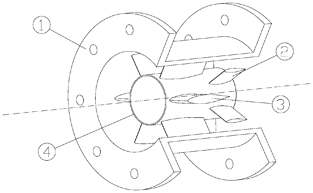
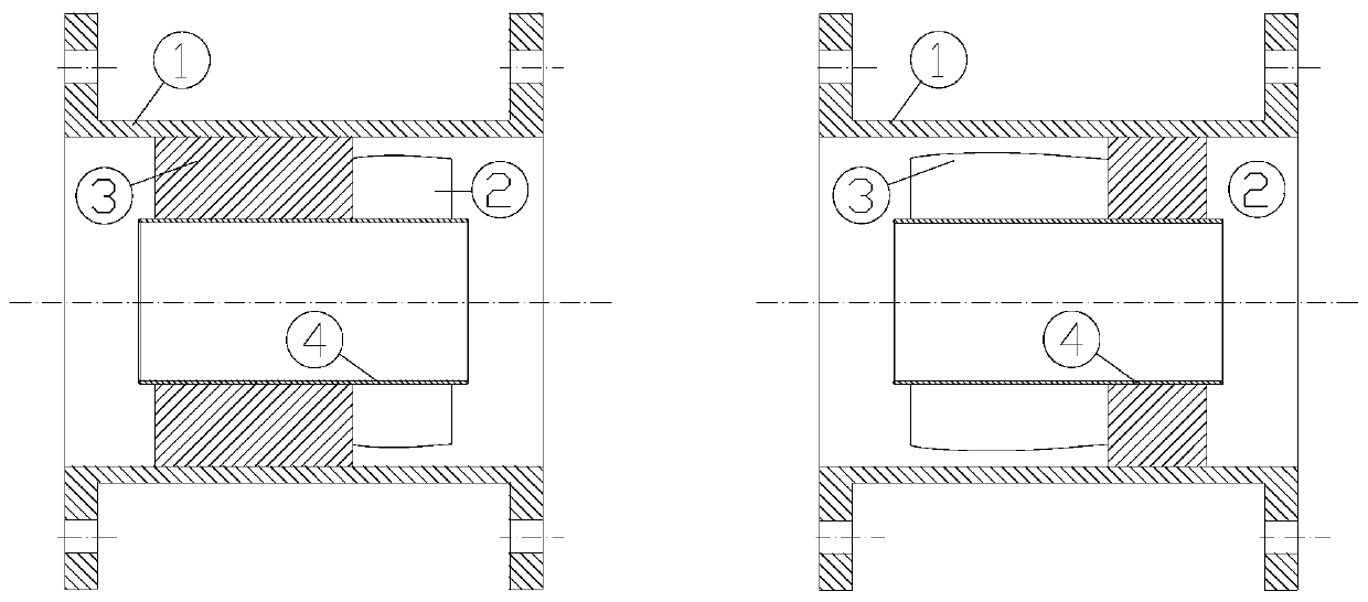
[0022] A flow field uniform device designed with large and small blades, the flow field uniform device includes a casing 1, a large blade 3, a small blade 2 and an inner liner 4, such as figure 1 shown;

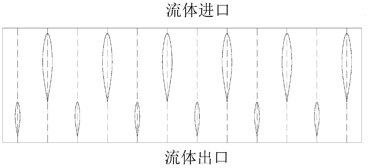
[0023] The cross-sectional shape of the small blade 2 and the cross-sectional shape of the large blade 3 are both NACA equal-thickness blades; the casing 1, the large blade 3, the small blade 2 and the lining pipe 4 are made of stainless steel;

[0024] The inner liner 4 is inside the casing 1, and the inner liner 4 and the casing 1 are connected through the large blade 3 and the small blade 2, and the two ends of the casing 1 are respectively fixedly connected to the external pipeline through flanges; The root of the blade 3 is welded to the outer surface of the lining pipe 4, and the tip of the blade is welded to the inner surface of the ca...


PUM


Abstract

The invention relates to a flow field uniformizing device adopting design of large blades and small blades and belongs to the field of control of flow fields of pipe filling pipelines. The flow field uniformizing device comprises a casing pipe, the large blades, the small blades and a lining pipe, wherein the large blades and the small blades are distributed and fixed in the circumferential direction between the casing pipe and the lining pipe, a vortex system can be cut and scattered on multiple rows of front and rear blades through reasonable blade distribution and blade shape design, and large vortexes are changed into small vortexes; a fluid close to the central position of a flow channel flows through the lining pipe, the flow regulation effect of the flow uniformizing device in the center position is enhanced through a flow regulation function of a longer cylindrical flow channel of the lining pipe, and finally, the purpose of flow field uniformizing is achieved. The flow field uniformizing device is compact in structure, requires small mounting space and is suitable for being mounted at an inlet end of a pump inlet with poorer flow inlet state and a downstream position of a valve.

Description

technical field [0001] The invention relates to a flow field uniform device designed by adopting large and small blades and installed in a position where the fluid flow state is poor in a pipeline, belonging to the field of flow field control of liquid-filled pipelines. Background technique [0002] Rotating equipment such as water pumps and water turbines are typical turbomachinery, and their vibration and noise levels are not only affected by mechanical factors such as rotor dynamic balance, but also the velocity field state of the working fluid inlet section is also the main factor affecting its vibration level. The purpose of optimizing the inflow state of the working fluid is to improve the uniformity of the inflow fluid. The parameters for evaluating the inflow state mainly include the axial velocity distribution, average axial velocity angle, pressure distribution, and unsteady velocity fluctuation of the inflow end surface. For turbomachinery, the unreasonable inflow...

Claims


Application Information

Patent Timeline
Patent Type & Authority Patents(China)
IPC IPC(8): F16L55/027
CPCF16L55/027
Inventor 刘海建陶襄樊徐俊姚伍平卢兆刚吴书有
Owner NO 719 RES INST CHINA SHIPBUILDING IND
Why Eureka
Try Eureka