Mounting structure of fabricated lamp trough decorative line

A technology of decorative lines and installation structures, which is applied to building components, building structures, buildings, etc., can solve the problems of cumbersome production, sagging of plates, and difficult quality control of degraded light troughs, so as to achieve simple construction process, solve material waste, The effect of saving resources

Pending Publication Date: 2020-04-28
GOLD MANTIS FINE DECORATION TECH SUZHOU CO LTD
View PDF0 Cites 3 Cited by
  • Summary
  • Abstract
  • Description
  • Claims
  • Application Information

AI Technical Summary

Problems solved by technology

[0004] In view of this, the present invention provides an installation structure for the decorative lines of the assembled light trough, which can effectively solve the problems of difficult quality control and cumbersome production of the downgraded light trough, and can also solve the problem of sagging of the board, so as to improve the installation efficiency and purpose of quality

Method used


Image

  • Mounting structure of fabricated lamp trough decorative line
  • Mounting structure of fabricated lamp trough decorative line
  • Mounting structure of fabricated lamp trough decorative line

Examples


Embodiment 1

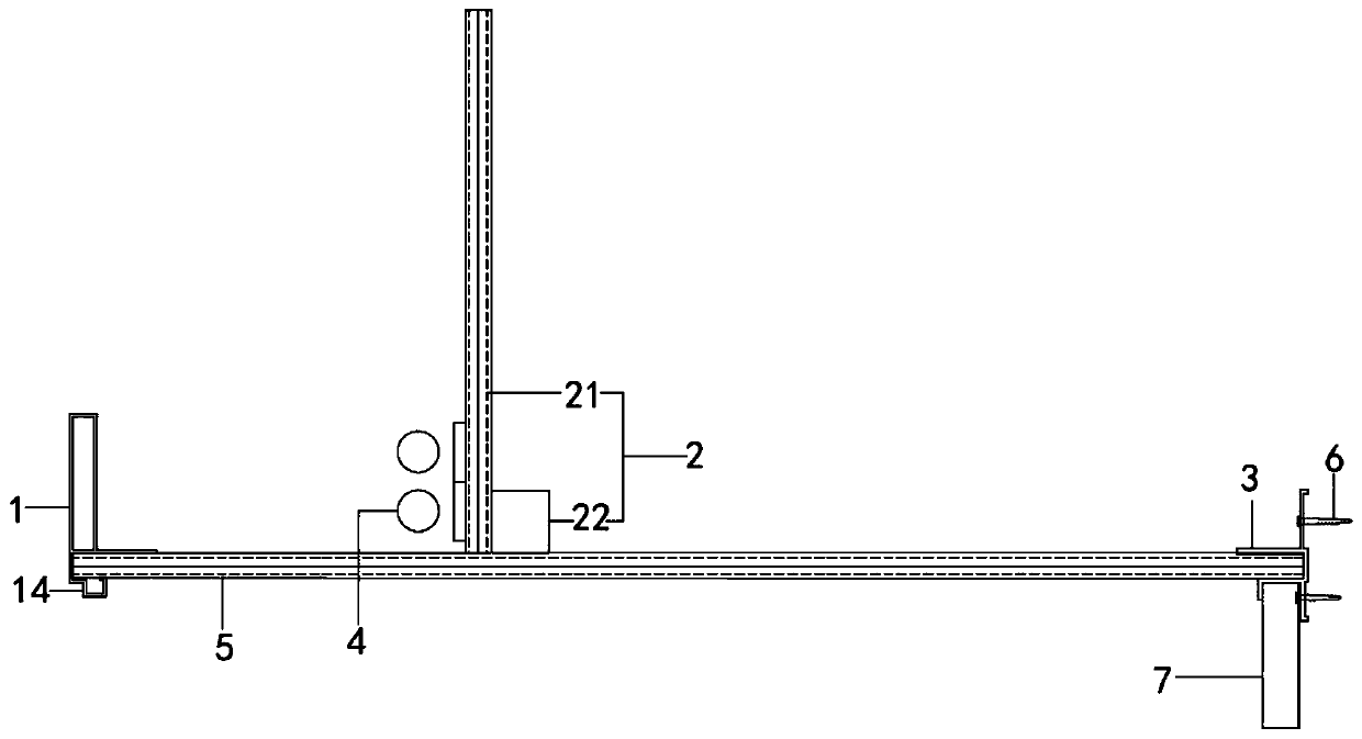
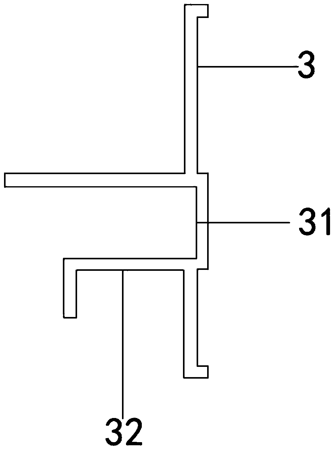
[0027] See Figure 1 to Figure 3 , The figure shows a mounting structure of the assembly-type lamp trough moldings according to an embodiment of the present invention, which mainly includes a light trough molding 1, a first fixing member 2 and a second fixing member 3. The first fixing member 2 includes The first connecting plate 21 and the second connecting plate 22, the first connecting plate 21 is fixedly connected with at least one light strip 4, the bottom of the first connecting plate 21 is connected to the second connecting plate 22, and the bottom of the second connecting plate 22 is fixedly connected There is a first decorative panel 5, one end of the first decorative panel 5 is connected to the second fixing member 3, and the other end of the first decorative panel 5 is connected to the light trough molding 1. The light trough molding 1 includes a first decorative plate 11 and The second decorative board 12, the second decorative board 12 is fixedly connected to the b...

Embodiment 2

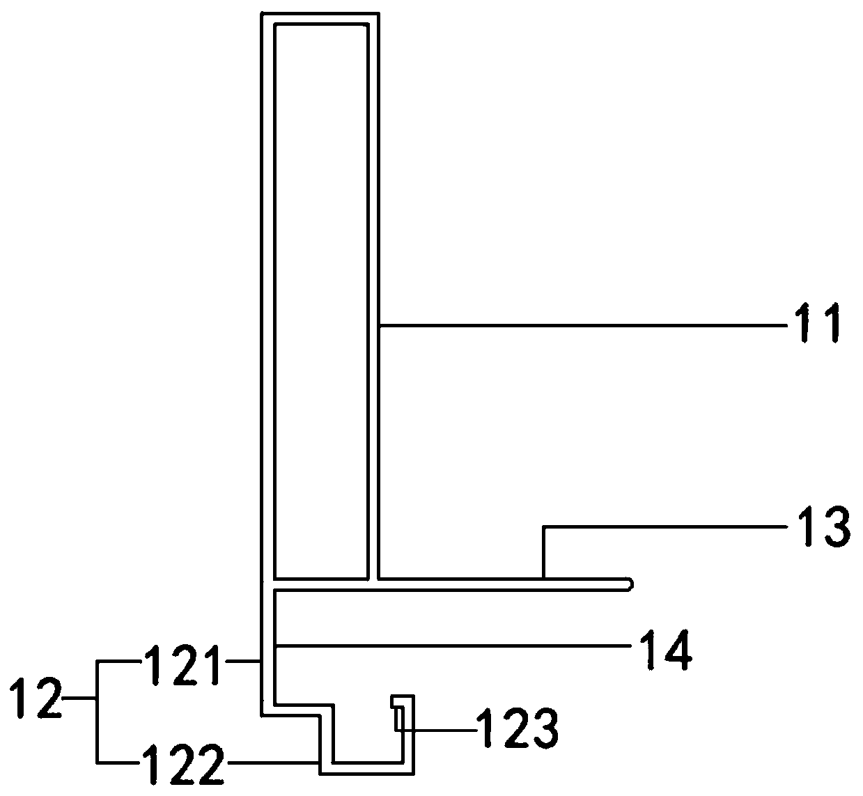
[0036] See Figure 1 to Figure 3 , The figure shows a mounting structure of a fabricated lamp trough decorative line provided by the second embodiment of the present invention. On the basis of the foregoing embodiments, this embodiment further makes the following as an improved technical solution: A third decorative board 13 extends horizontally at the bottom of a decorative board 11, the third decorative board 13 abuts the first decorative board 5, and the first decorative board 11, the second decorative board 12 and the third decorative board 13 are integrally formed.

[0037] Through the arrangement of the above structure, the third decorative panel extends out of the first decorative panel and contacts the top of the first decorative panel, which can increase the contact area between the first decorative panel and the third decorative panel, and achieve the effect of improving the friction between the two , And then achieve the purpose of improving the quality of installation...

Embodiment 3

[0039] See Figure 1 to Figure 3 , The figure shows a mounting structure of a fabricated lamp trough decorative line provided by the third embodiment of the present invention. This embodiment further makes the following as an improved technical solution on the basis of the foregoing embodiments: The second decorative board 12 includes an L-shaped decorative board 121 and a “mouth”-shaped decorative board 122. The “mouth”-shaped decorative board 122 is vertically connected to the bottom of the L-shaped decorative board 121. The right side of the “mouth”-shaped decorative board 122 is higher than the left side. A baffle 123 extends on the right side of the “mouth”-shaped decorative board 122. In this way, after the first decorative panel is glued and bonded in the slot, after the glue is cured, since the height of the right side of the mouth-shaped decorative panel is higher than the left, the right side extends with a baffle, which forms a clamping structure with the cured glue ...


PUM


Abstract

The invention provides a mounting structure of a fabricated lamp trough decorative line. The mounting structure comprises the lamp trough decorative line, a first fixing piece and a second fixing piece, wherein the first fixing piece comprises a first connecting plate and a second connecting plate, at least one lamp strip is fixedly connected to the first connecting plate, the bottom of the firstconnecting plate is connected to the second connecting plate, a first facing plate is fixedly connected to the bottom of the second connecting plate, one end of the first facing plate is connected tothe second fixing piece, the other end of the first facing plate is connected to the lamp trough decorative line, the lamp trough decorative line comprises a first decorative plate and a second decorative plate, the second decorative plate is fixedly connected to the bottom of the first decorative plate, a begonia-like corner is arranged on the second decorative plate, a clamping groove is formedbetween the first decorative plate and the second decorative plate, and the end part of the first facing plate is inserted into the clamping groove. According to the mounting structure of the fabricated lamp trough decorative line, compared with the prior art, the problems that the quality of a falling lamp trough is difficult to control, and manufacturing of the falling lamp trough is tedious canbe effectively solved, and the problem of plate dropping can further be solved.

Description

Technical field [0001] The invention relates to the technical field of building decoration, in particular, to an installation structure of a fabricated lamp trough decorative line. Background technique [0002] Assembled decoration is a new form of decoration construction in recent years. As the name implies, assembly decoration is to complete the production of various parts and components required for decoration in the factory, and then transport them to the decoration site for assembly installation, eliminating the need for traditional decoration sites to measure and cut various parts and components. The construction is simpler and more convenient, can greatly improve the construction efficiency of the decoration site, and the construction site is more tidy and beautiful, and does not generate too much decoration material garbage. It is a more green and environmentally friendly form of decoration construction. [0003] The drop-down lamp trough is an indispensable decorative met...

Claims


Application Information

Patent Timeline
Patent Type & Authority Applications(China)
IPC IPC(8): E04B9/00E04B9/06E04B9/22E04B9/30E04B9/18
CPCE04B9/006E04B9/06E04B9/18E04B9/22E04B9/30
Inventor 汪建垚佘予然何志伟于利凯
Owner GOLD MANTIS FINE DECORATION TECH SUZHOU CO LTD
Why Eureka
Try Eureka