
Safety auxiliary device for electric power tower maintenance

A technology for power towers and auxiliary devices, applied to towers, ladders, building types, etc., can solve the problems of hidden dangers for maintenance personnel, poor force application, high cost, etc., and achieve convenient maintenance and operation, good protection effect, and good protection effect Effect

Active Publication Date: 2020-04-28
RES INST OF ECONOMICS & TECH STATE GRID SHANDONG ELECTRIC POWER +3
View PDF6 Cites 4 Cited by
  • Summary
  • Abstract
  • Description
  • Claims
  • Application Information

AI Technical Summary

Problems solved by technology

[0002] The current electric power maintenance device is generally equipped with a ladder on the tower. During maintenance, workers climb from the ladder to the top of the tower for maintenance. During the climbing process, there is a great safety risk due to the lack of protective devices. The safety of maintenance personnel has caused great hidden dangers, and during the maintenance process, maintenance personnel are also hung on the tower with safety ropes. The protective device is relatively simple, and it is not easy to apply force during the maintenance process, which brings great harm to the maintenance. Inconvenient, the prior art also has an improvement for this problem, and the super-high lifting device will be used to send the maintenance personnel to the top, which greatly reduces the danger of climbing, but the cost of this operation is high and a lot of manpower is wasted Material resources, it is difficult to meet the needs of simultaneous maintenance of a large number of towers

Method used


Image

  • Safety auxiliary device for electric power tower maintenance
  • Safety auxiliary device for electric power tower maintenance
  • Safety auxiliary device for electric power tower maintenance

Examples


Embodiment Construction

[0025] Below in conjunction with specific embodiment, further illustrate the present invention. It should be understood that these examples are only used to illustrate the present invention and are not intended to limit the scope of the present invention. In addition, it should be understood that after reading the content taught by the present invention, those skilled in the art may make various changes or modifications to the present invention, and these equivalent forms also fall within the scope defined in the present application.

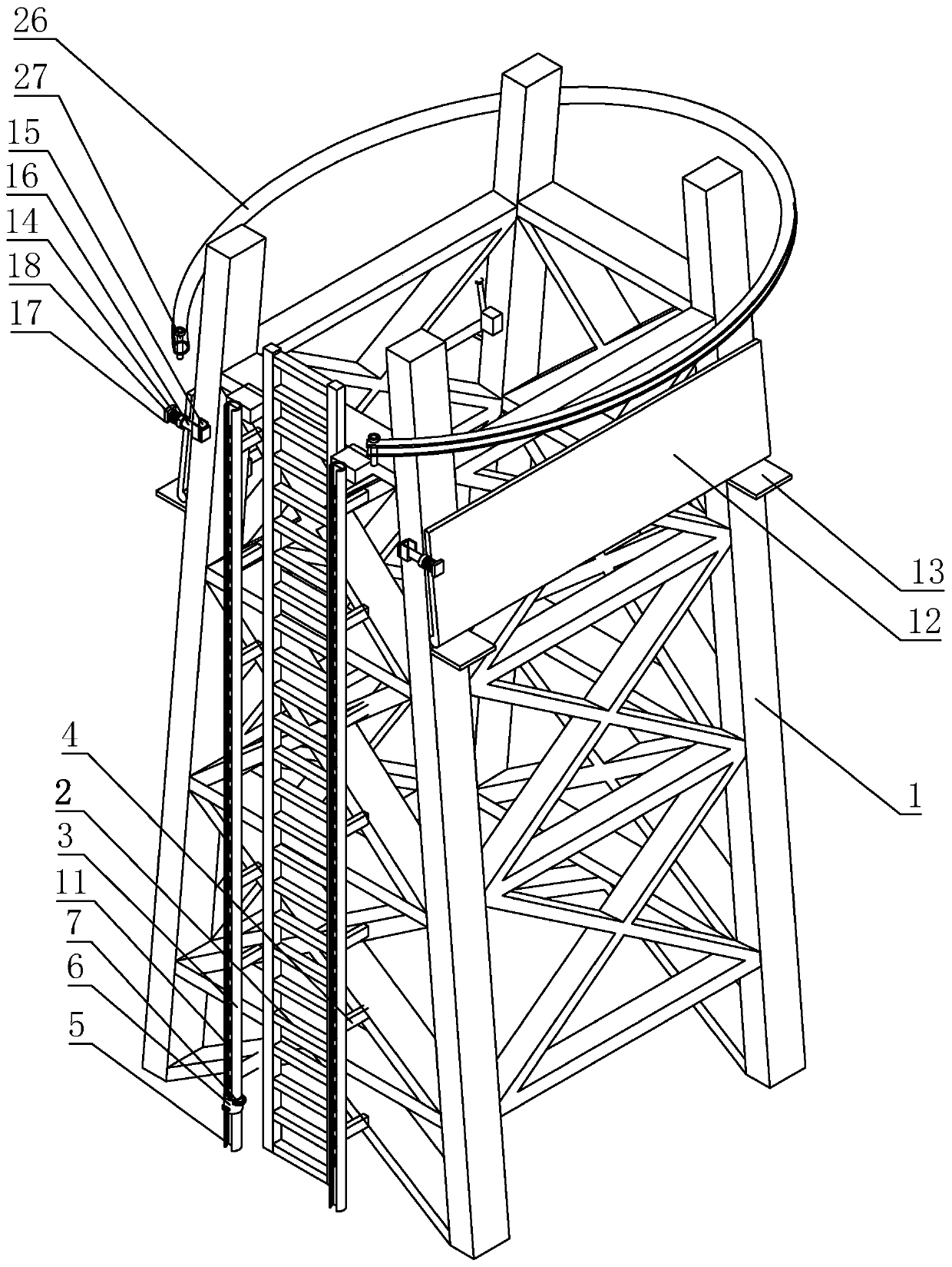
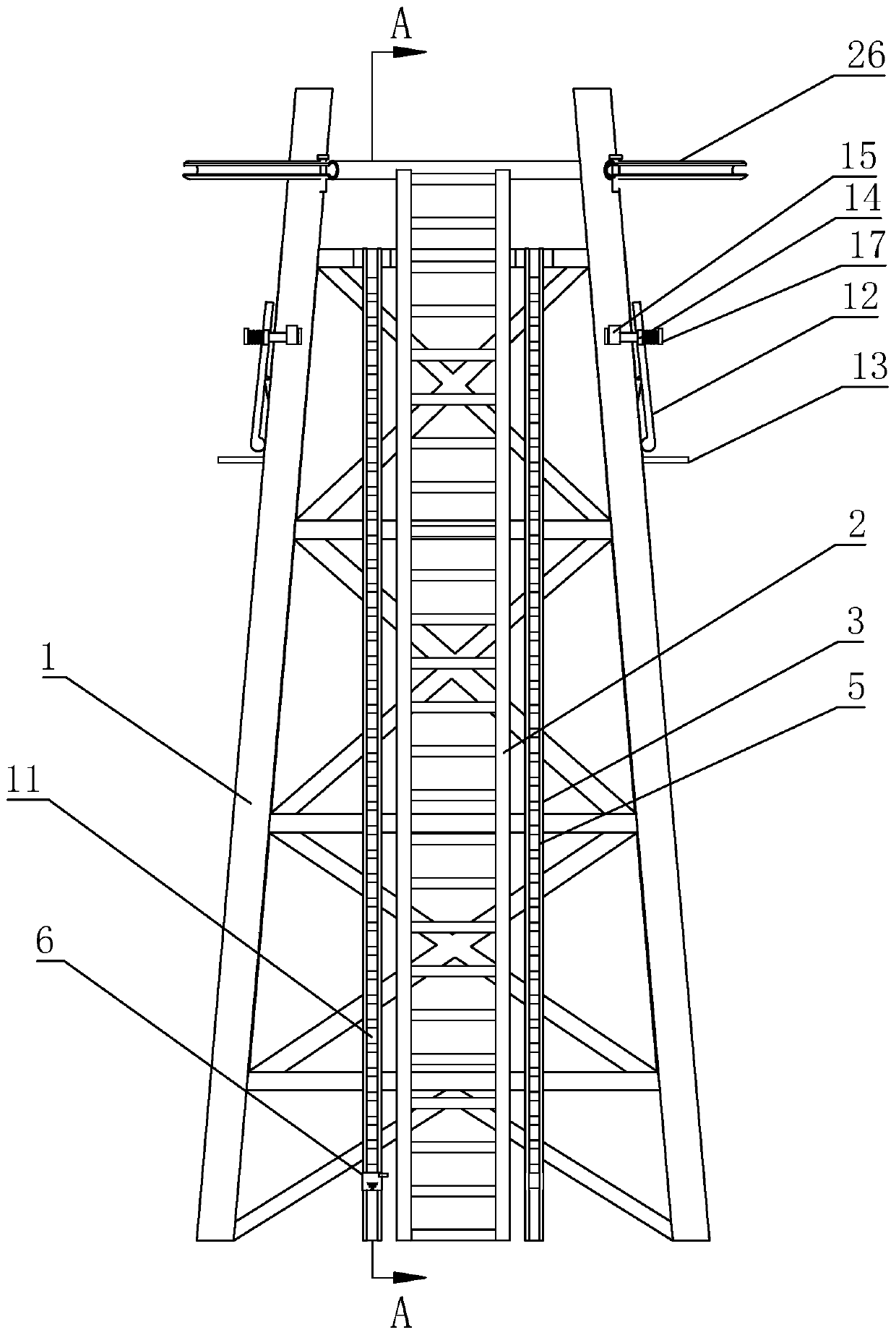
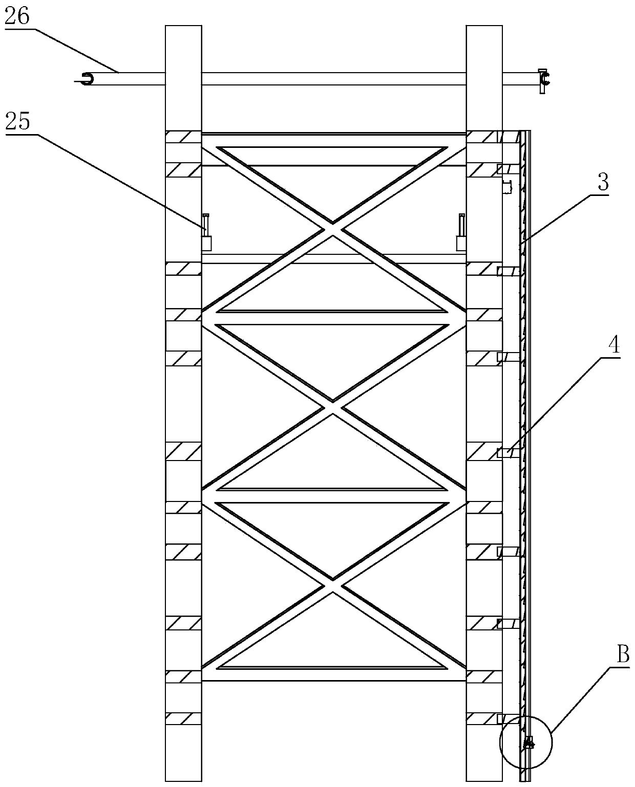
[0026] The present invention is a safety auxiliary device for power tower maintenance, the main structure includes a tower 1, the bottom of the tower 1 is buried under the ground through concrete, and the specific tower 1 is the same as the existing tower The frame structure is the same, and more suitable for angle steel towers. One side of the tower 1 is provided with a ladder 2 along its height direction. The ladder 2 is fixed on the tower 1 b...


PUM


Abstract

The invention discloses a safety auxiliary device for electric power tower maintenance, and mainly relates to the field of electric power equipment. The safety auxiliary device comprises a tower, wherein a ladder stand is arranged on one side of the tower in the height direction of the tower. The safety auxiliary device further comprises an anti-skid structure and a standing structure, wherein theanti-skid structure comprises protective pipes; the protective pipes are symmetrically fixed on the two sides of the ladder stand; fixing columns are arranged between the protective pipes and the tower; sliding holes are formed in the protective pipes in the length direction; sliding buckles are connected to the protective pipes in a sliding mode in the length direction of the protective pipes; fixing lugs are arranged on one sides of the sliding buckles; the sliding buckles sleeve the outer sides of the protective pipes; notches are formed in the sides, facing the tower, of the sliding buckles; sliding blocks are arranged on the inner sides of the sliding buckles and are connected in the sliding holes in a sliding mode; anti-skid plates are rotationally connected to the sliding blocks; aplurality of anti-skid grooves are linearly arrayed in the protective pipes in the length direction; and the anti-skid grooves are in a shape with a shallow upper part and a deep lower part. The safety auxiliary device has the beneficial effects that more safety guarantees are provided for maintenance personnel in the climbing and maintenance process, and potential safety hazards are reduced.

Description

technical field [0001] The invention relates to the field of electric equipment, in particular to a safety auxiliary device for power tower maintenance. Background technique [0002] The current electric power maintenance device is generally equipped with a ladder on the tower. During maintenance, workers climb from the ladder to the top of the tower for maintenance. During the climbing process, there is a great safety risk due to the lack of protective devices. The safety of maintenance personnel has caused great hidden dangers, and during the maintenance process, maintenance personnel are also hung on the tower with safety ropes. The protective device is relatively simple, and it is not easy to apply force during the maintenance process, which brings great harm to the maintenance. Inconvenient, the prior art also has an improvement for this problem, and the super-high lifting device will be used to send the maintenance personnel to the top, which greatly reduces the danger...

Claims


Application Information

Patent Timeline
IPC IPC(8): E04H12/00E06C7/18
CPCE04H12/00E06C7/186E06C7/187
Inventor 孙启刚宋卓彦朱毅朱子剑
Owner RES INST OF ECONOMICS & TECH STATE GRID SHANDONG ELECTRIC POWER
Learn More