
X-ray flat panel detector and preparation method

A flat panel detector and X-ray technology, applied in radiation intensity measurement, radiation control devices, electric solid devices, etc., to achieve the effect of reducing afterglow

Pending Publication Date: 2020-04-28
SHANGHAI IRAY TECH
View PDF0 Cites 2 Cited by
  • Summary
  • Abstract
  • Description
  • Claims
  • Application Information

AI Technical Summary

Problems solved by technology

[0004] However, the CsI:Tl scintillator material has an afterglow phenomenon, and the TFT substrate also has an afterglow phenomenon after being irradiated by the fluorescence emitted by CsI:Tl. The afterglow of the two becomes the afterglow of the X-ray flat panel detector. Among them, The afterglow will have a negative impact on the performance of the X-ray flat panel detector, so it is necessary to provide a new type of X-ray flat panel detector and its preparation method to try to reduce the afterglow phenomenon of the X-ray flat panel detector

Method used


Image

  • X-ray flat panel detector and preparation method
  • X-ray flat panel detector and preparation method
  • X-ray flat panel detector and preparation method

Examples


preparation example Construction

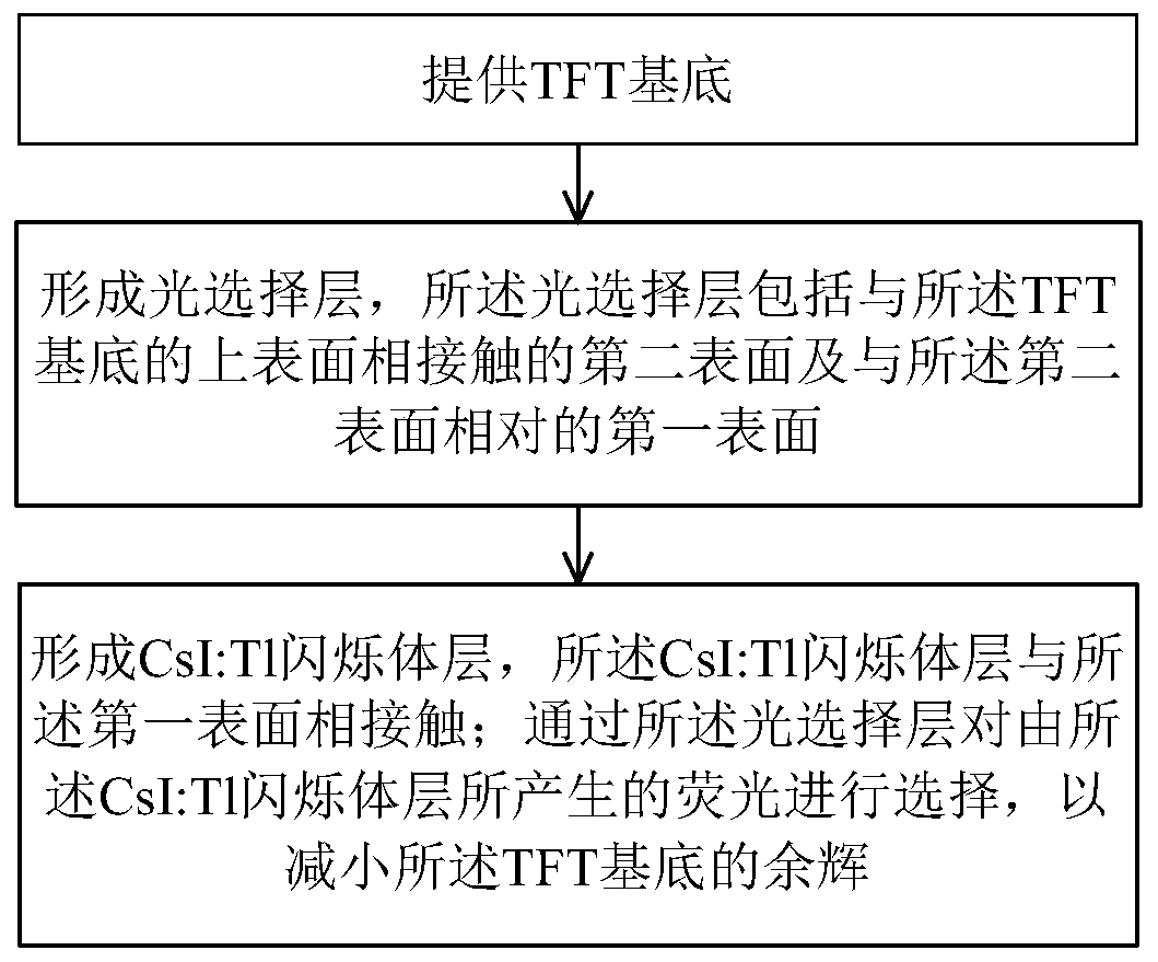
[0034] Based on the above analysis, the present invention provides a novel X-ray flat panel detector and its preparation method, which can prevent or reduce the blue light, purple light and near ultraviolet light emitted by the CsI:T1 film by absorbing or reflecting blue light, purple light and near ultraviolet light Irradiate to the TFT substrate, thereby reducing the afterglow of the TFT substrate, so as to reduce the afterglow of the X-ray flat panel detector.

[0035] Embodiments of the present invention are described below through specific examples, and those skilled in the art can easily understand other advantages and effects of the present invention from the content disclosed in this specification. The present invention can also be implemented or applied through other different specific implementation modes, and various modifications or changes can be made to the details in this specification based on different viewpoints and applications without departing from the spir...

Embodiment 2

[0063] 2-1. Provide the TFT substrate mentioned in 1-1, with a thickness of 0.7mm;

[0064] 2-2. Place a piece of PVC film with a thickness of 10 μm on the TFT substrate;

[0065] 2-3. Place the CsI:Tl scintillator film with a thickness of 500 μm in 1-2 on the PVC film;

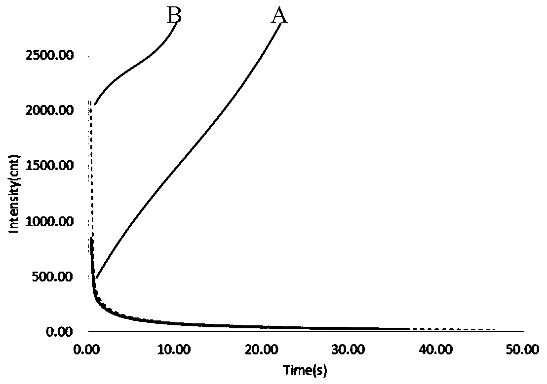
[0066] 2-4. Repeat the steps 1-3 and 1-4 to record the change of the gray value of the TFT substrate over time, such as image 3 The B curve in .

[0067] Depend on image 3 It can be seen that in the A curve, the initial value is 2085cnt; in the B curve, the initial value is 842cnt; therefore, using the X-ray flat panel detector prepared by the present invention can reduce the afterglow of the TFT substrate to the original 40 %, so that the afterglow of the TFT substrate can be effectively reduced by the light selective layer, so as to reduce the afterglow of the X-ray flat panel detector.

[0068] In summary, in the X-ray flat panel detector and the preparation method of the present invention, the photo...


PUM

PropertyMeasurementUnit
Thicknessaaaaaaaaaa
Thicknessaaaaaaaaaa
Thicknessaaaaaaaaaa

Abstract

The invention provides an X-ray flat panel detector and a preparation method. The X-ray flat panel detector comprises a TFT substrate, a CsI:Tl scintillator layer and a light selection layer, whereinthe CsI:Tl scintillator layer is enabled to be in contact with the first surface of the light selection layer through the light selection layer, and the TFT substrate is in contact with the second surface of the light selection layer, so that fluorescence generated by the CsI:Tl scintillator layer is selected through the light selection layer, afterglow of the TFT substrate is reduced, and afterglow of the X-ray flat panel detector is reduced.

Description

technical field [0001] The invention belongs to the field of flat panel detectors, and relates to an X-ray flat panel detector and a preparation method. Background technique [0002] The detection and imaging of X-rays enable humans to detect the internal information of objects. In general, an X-ray flat panel detector is a detector that uses semiconductor technology to convert X-ray energy into electrical signals and generate X-ray images. With the development of society and the advancement of science and technology, X-ray flat panel detectors play an extremely important role in the fields of medical imaging and industrial flaw detection. [0003] A scintillator is a material that can convert the energy of high-energy particles (such as protons, neutrons, electrons, etc.) or high-energy rays (such as X-rays, γ-rays, etc.) into ultraviolet or visible light. application. Cesium iodide (CsI) series scintillators are colorless and transparent cubic crystals with high density ...

Claims


Application Information

Patent Timeline
IPC IPC(8): H01L27/146G01T1/20
CPCH01L27/14663H01L27/14621H01L27/14689G01T1/20Y02P70/50
Inventor 甘新式程丙勋钟良兆杨炯灿
Owner SHANGHAI IRAY TECH
Learn More