
Communication equipment mounting bracket convenient to adjust

A communication equipment and mounting bracket technology, applied in the field of communication equipment mounting brackets, can solve the problems of different structures of communication equipment functions, damage, equipment damage, etc., and achieve the effects of convenient maintenance and replacement, convenient use, and avoidance of rotation.

Inactive Publication Date: 2020-04-28
李萍
View PDF0 Cites 0 Cited by
  • Summary
  • Abstract
  • Description
  • Claims
  • Application Information

AI Technical Summary

Problems solved by technology

[0002] Communication equipment is wired communication equipment and wireless communication equipment used in industrial control environments. When communication equipment is installed outdoors, it is usually fixed in a communication box, and the communication box is installed on a mounting frame. However, with the continuous development of the electronic technology field, The function and structure of communication equipment are different, especially the manufacturers design communication equipment with the same shape and structure in order to improve customer satisfaction while satisfying the function. Therefore, when using and installing, due to the size of various communication equipment Similarly, the traditional installation frame cannot meet the needs. In addition, because the outdoor communication cabinet is installed outdoors, it is easy to be damaged by uncertain factors and external forces, resulting in damage to the equipment in the cabinet, and the existing installation method is not easy for communication equipment. The cabinet is repaired and replaced, so a conveniently adjustable communication equipment mounting bracket is needed to improve the above problems

Method used


Image

  • Communication equipment mounting bracket convenient to adjust
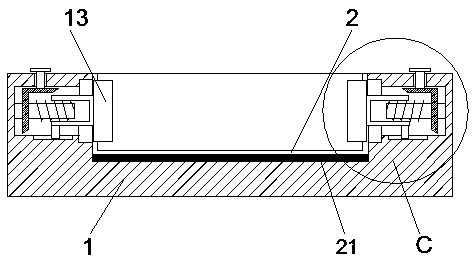
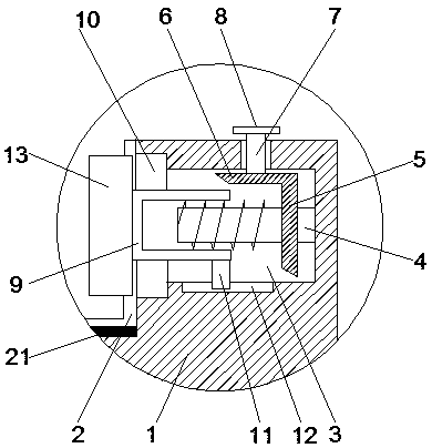
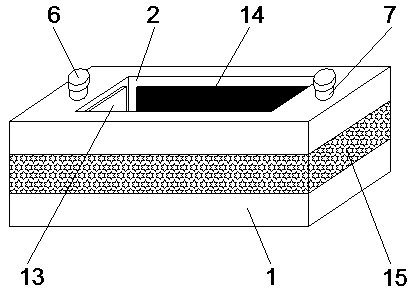
  • Communication equipment mounting bracket convenient to adjust
  • Communication equipment mounting bracket convenient to adjust

Examples


Embodiment Construction

[0020] The technical solutions in the embodiments of the present invention will be clearly and completely described below in conjunction with the accompanying drawings in the embodiments of the present invention. Obviously, the described embodiments are only some of the embodiments of the present invention, not all of them. Based on The embodiments of the present invention and all other embodiments obtained by persons of ordinary skill in the art without making creative efforts belong to the protection scope of the present invention.

[0021] see Figure 1-3 , the present invention provides a technical solution:

[0022] A conveniently adjustable mounting bracket for communication equipment, comprising a fixed base 1, a fixed groove 2, a block 13, wear-resistant rubber 15 and a warning tape 16, the fixed base 1 is provided with a fixed groove 2, and the bottom of the fixed groove 2 A magnet 21 is provided, through the set fixed base 1 and the fixed groove 2, the effect of pla...


PUM


Abstract

The invention relates to the technical field of communication equipment, in particular to a communication equipment mounting bracket convenient to adjust. The mounting bracket comprises a fixed base,a fixed groove, a clamping block, wear-resistant rubber and a warning tape, the fixed groove is formed in the fixed base, a magnet is arranged at the bottom of the fixed groove, groove bodies are formed in the two sides of the interior of the fixed base correspondingly. One side of an inner cavity of each groove body is movably connected with a threaded rod; the surface of the threaded rod is sleeved with a first bevel gear. A second bevel gear used in cooperation with the first bevel gear is arranged at the top of an inner cavity of each groove body. The top of the second bevel gear is fixedly connected with a connecting rod, the top of the connecting rod sequentially penetrates through each groove body and the fixed base and extends to the exterior of the fixed base to be fixedly connected with a rotating disc, and the surface of each threaded rod is sleeved with a threaded pipe. The whole mounting bracket is simple in structure and convenient to operate, and has a certain popularization value.

Description

technical field [0001] The invention relates to the technical field of communication equipment, in particular to a conveniently adjustable communication equipment mounting bracket. Background technique [0002] Communication equipment is wired communication equipment and wireless communication equipment used in industrial control environments. When communication equipment is installed outdoors, it is usually fixed in a communication box, and the communication box is installed on a mounting frame. However, with the continuous development of the electronic technology field, The function and structure of communication equipment are different, especially the manufacturers design communication equipment with the same shape and structure in order to improve customer satisfaction while satisfying the function. Therefore, when using and installing, due to the size of various communication equipment Similarly, the traditional installation frame cannot meet the needs. In addition, bec...

Claims


Application Information

Patent Timeline
Patent Type & Authority Applications(China)
IPC IPC(8): H04B1/3877
CPCH04B1/3877
Inventor 李萍
Owner 李萍
Learn More