Tunnel communication repeater

A technology of repeaters and tunnels, which is applied in the direction of radio transmission systems, electrical components, transmission systems, etc., can solve problems such as the loss of protection of the dust-proof net, the influence of the normal operation of the repeater, and the entry of dust, so as to avoid normal heat dissipation Effect

Active Publication Date: 2020-04-28
UNIV FOR SCI & TECH ZHENGZHOU
View PDF11 Cites 4 Cited by
  • Summary
  • Abstract
  • Description
  • Claims
  • Application Information

AI Technical Summary

Problems solved by technology

[0003] Due to the complex environment in the railway tunnel, we usually set the communication repeater in the dust-proof net to prevent dust, sundries and other small animals such as insects in the tunnel from entering the communication repeater and affecting the repeater Normally, the dust-proof net can only be used to prevent the entry of dust when the air in the tunnel is static. When the air in the tunnel is static, a large amount of dust in the tunnel will accumulate on the tunnel wall and the bottom wall of the tunnel. Above, there is only a small amount of dust in the air and it is in a free-floating state. At this time, it is difficult for the dust to pass through the dust-proof net and enter the repeater;
[0004] However, because some high-speed trains often pass through the railway tunnel, when the high-speed train passes through the tunnel, it will drive the airflow in the tunnel to flow at a high speed, and the high-speed airflow will drive the dust deposited in the tunnel to move synchronously, so that the dust in the tunnel Under the action of high-speed airflow, it passes through the dust-proof net and enters the repeater. That is, when a high-speed train passes through the railway tunnel, the dust-proof net loses its protective effect. Over time, there will be accumulated dust in the communication repeater. More dust, and affect the normal work of the repeater;
[0005] In view of the above, we provide a tunnel communication repeater to solve the problem that dust easily passes through the dust-proof net and enters the repeater when a high-speed train passes through the tunnel

Method used


Image

  • Tunnel communication repeater
  • Tunnel communication repeater
  • Tunnel communication repeater

Examples


Embodiment 1

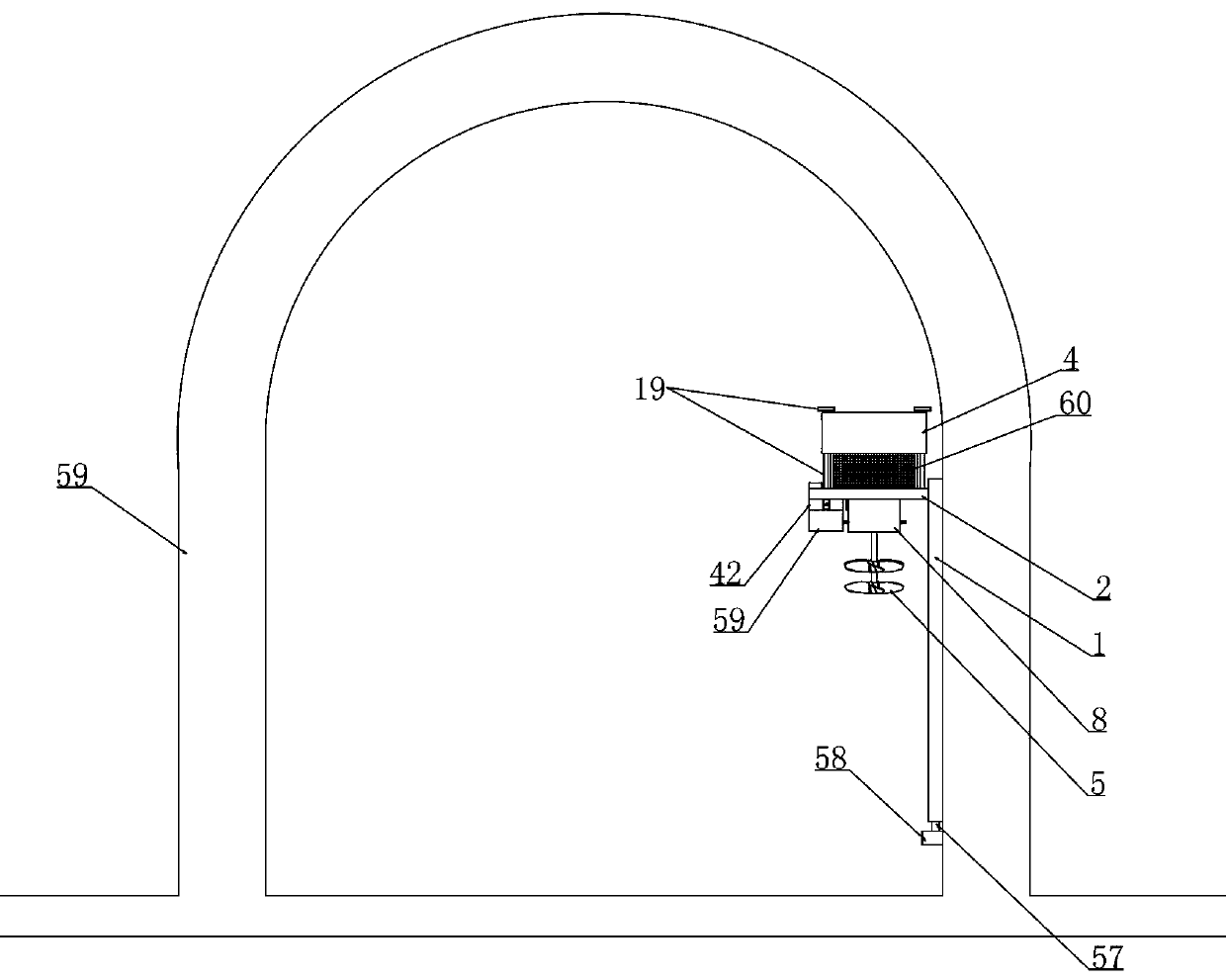
[0048] Embodiment 1, this embodiment provides a tunnel communication repeater, refer to the attached figure 1 As shown, it includes a slideway 1 fixedly installed on the side wall of the tunnel and a bearing plate 2 is vertically slidably installed in the slideway 1, and a communication host 3 is fixedly installed on the bearing plate 2. We control the bearing plate 2 in the sliding Vertically move in the channel 1, and then drive the communication host 3 to move vertically. When the communication host 3 needs to be inspected and maintained, the communication host 3 will be moved down to facilitate maintenance personnel to perform inspection and maintenance operations on it. The bottom of the bearing plate 2 is provided with an outlet (not shown in the figure), and the data line connected to the communication host 3 protrudes outward through the outlet. It is characterized in that we vertically slide and install a protective The cover 4 and the carrier plate 2 are provided wit...

Embodiment 2

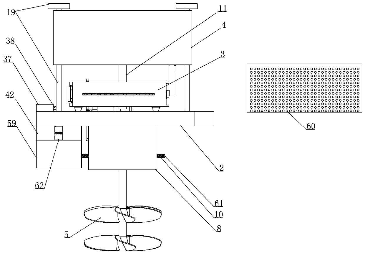
[0055]Embodiment 2, on the basis of embodiment 1, with reference to appended Figure 8 As shown, four guide columns 19 are fixed on the upper end surface of the bearing plate 2 and the protective cover 4 is vertically slidably installed on the four guide columns 19, referring to the attached Figure 10 As shown, when the positioning device realizes the positioning of the protective cover 4, the L-shaped rod 20 is inserted into the L-shaped hole 22 that cooperates with it and is arranged on the protective cover 4, as attached Figure 10 As shown, when several trigger balls 7 are in contact with the arc-shaped trigger plate 9, the L-shaped bar 20 is moved toward the direction of the compression positioning spring 21 and the horizontal part of the L-shaped bar 20 is withdrawn from the horizontal part of the L-shaped hole 22, Now protective cover 4 loses the location of L-shaped bar 20 to it, then protective cover 4 moves down along guide bar under its own gravity, thereby realize...

Embodiment 3

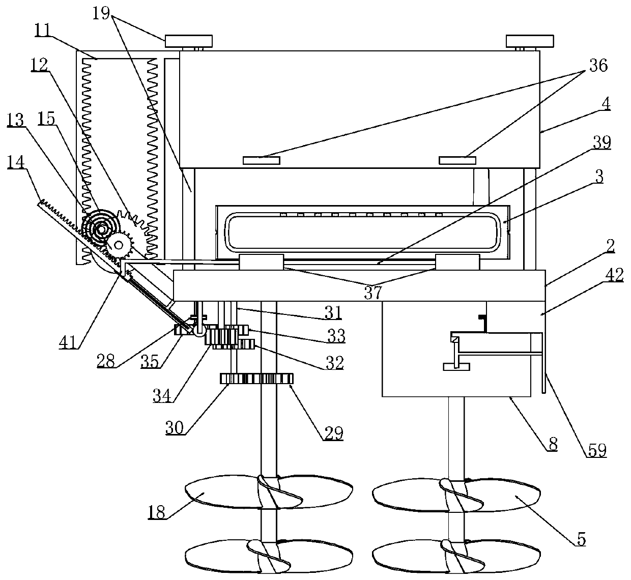
[0056] Embodiment 3, on the basis of Embodiment 2, in this solution, four trigger balls 7 are arranged in total and correspond to four guide columns 19 respectively, and the two arc-shaped trigger plates 9 do not contact in the initial state (as shown in the attached Figure 11 As shown), we connect the L-shaped rod 20 with the positioning spring 21 and fix the iron plate on the side wall, refer to the attached Figure 12 As shown, when the air in the tunnel is static, that is, when the high-speed train is not passed, some trigger balls 7 are not in contact with the arc trigger plate 9, when the high-speed train is passed in the tunnel, the high-speed airflow generated drives the trigger fan blade 5 to rotate and Synchronously drive a number of bearing rods 23 fixed on the outer wall of the ring 6 to rotate, and then throw the trigger ball 7 fixedly mounted on the swing rod 24 outward through centrifugal force so that the trigger ball 7 touches the inner circle of the arc-shape...


PUM


Abstract

The invention relates to a tunnel communication repeater. The tunnel communication repeater effectively solves the problem that dust in a tunnel is likely to enter a repeater due to high-speed airflowgenerated by a communication repeater installed in a railway tunnel when a high-speed train passes through the repeater. According to the technical scheme, when the high-speed train does not pass through the railway tunnel, the dustproof net can carry out preliminary protection on the repeater; when a train running at a high speed passes through the tunnel, the train running at the high speed drives air flow in the tunnel to move at the high speed, the positioning device is released by triggering the fan blades, the protective cover slides down to seal and protect the repeater, and dust is effectively prevented from penetrating through the dustproof net under the action of the air flow moving at the high speed.

Description

technical field [0001] The invention relates to the technical field of communication transfer, in particular to a tunnel communication repeater. Background technique [0002] With the development of my country's railways, safe operation has become the primary task of railway operations. It is hoped that there will be no accidents during the operation of the train, and various equipment must be installed in the tunnel to monitor the situation in the tunnel. With the railway tunnel After the construction is completed and put into operation for a long time, we need to monitor the displacement and deformation of the rails and whether there are cracks on the inner wall of the tunnel in real time to ensure the safety and smoothness of the tunnel, so that no safety accidents will occur when the high-speed train passes through the tunnel. , the various monitoring equipment set up need to transmit the real-time monitoring information to the control room through communication cables. Wh...

Claims


Application Information

Patent Timeline
Patent Type & Authority Applications(China)
IPC IPC(8): H04Q1/08H04Q1/02H04B7/155
CPCH04B7/155H04Q1/035H04Q1/08H04Q1/11
Inventor 李江江李冰张亚超冯丽娟陈红友
Owner UNIV FOR SCI & TECH ZHENGZHOU
Why Eureka
Try Eureka