Hardware product electroplating processing system

A processing system and product technology, applied in the electrolysis process, electrolysis components, cells, etc., can solve the problems of failure to be electroplated and uneven electroplating of hardware workpieces, and achieve the effect of facilitating electroplating and solving uneven electroplating

Inactive Publication Date: 2020-05-01
孟文
View PDF10 Cites 0 Cited by
  • Summary
  • Abstract
  • Description
  • Claims
  • Application Information

AI Technical Summary

Problems solved by technology

[0003] The existing electroplating processing equipment for hardware products directly puts the metal workpiece to

Method used


Image

  • Hardware product electroplating processing system
  • Hardware product electroplating processing system
  • Hardware product electroplating processing system

Examples


Example Embodiment

[0026] Example 1

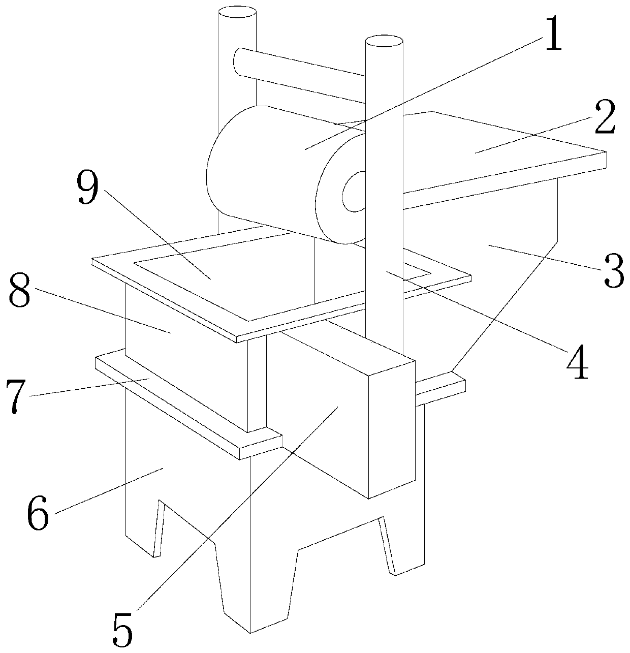
[0027] see Figure 1-Figure 6 , the present invention provides a metal product electroplating processing system, the structure of which includes a roller 1, a placement plate 2, a support block 3, a fixed frame 4, a motor box 5, a support foot 6, a connecting plate 7, a toggle device 8, and an electroplating box 9 , the roller 1 is installed on the fixed frame 4, the fixed frame 4 is mechanically welded with the connecting plate 7, the connecting plate 7 is located on the top of the supporting foot 6, the supporting foot 6 is fixedly connected with the connecting plate 7, and the connecting plate 7 An electroplating box 9 is arranged on the plate 7, a toggle device 8 is arranged in the electroplating box 9, the support block 3 is connected with the connecting plate 7, and a placement plate 2 is fixedly arranged on the support block 3;

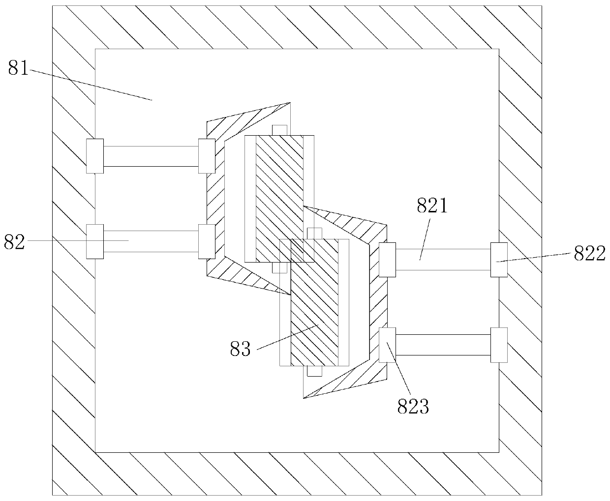
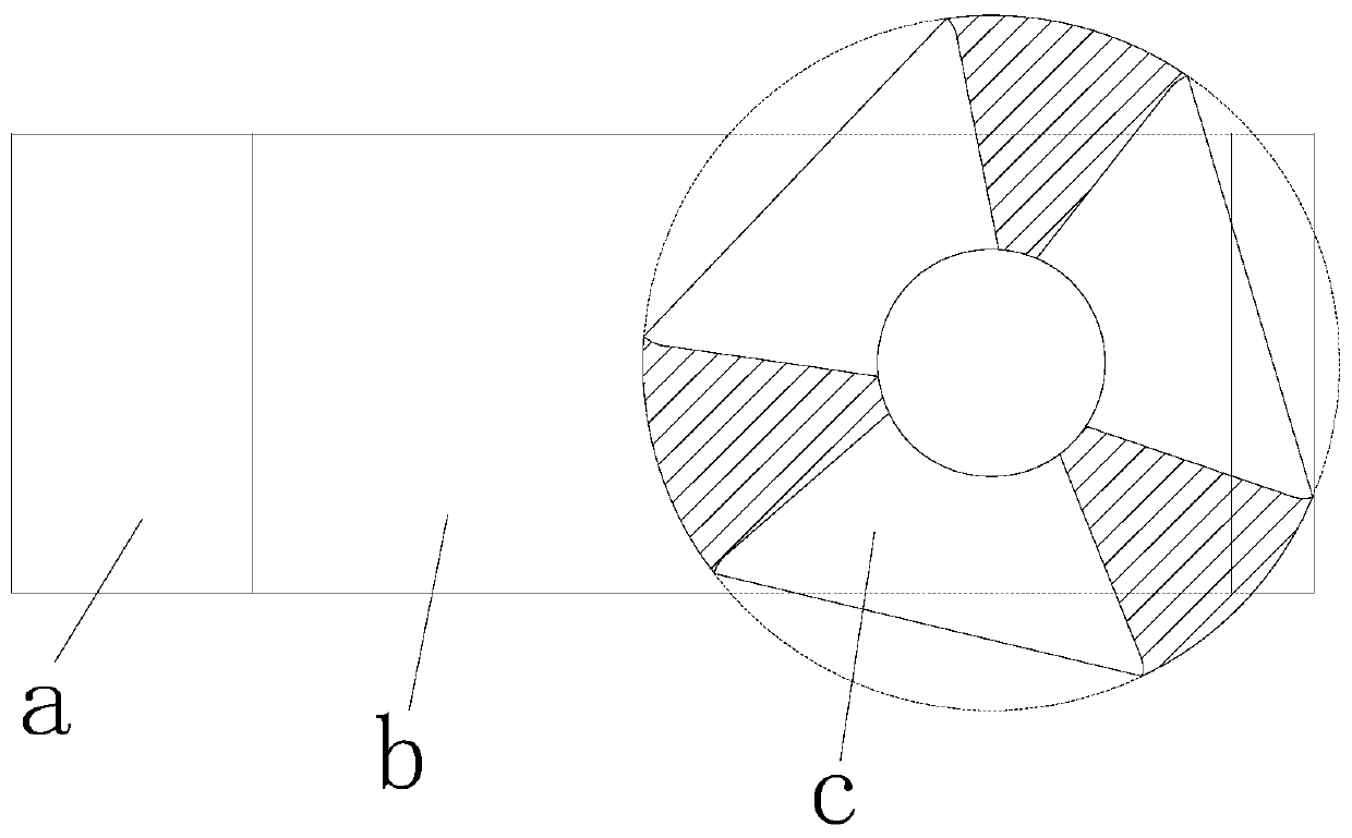
[0028] The toggle device 8 is composed of an electroplating bin 81, a connecting unit 82, and a toggle unit 83. The electr...

Example Embodiment

[0037] Example 2

[0038] see Figure 1-Figure 4 , the present invention provides a metal product electroplating processing system, the structure of which includes a roller 1, a placement plate 2, a support block 3, a fixed frame 4, a motor box 5, a support foot 6, a connecting plate 7, a toggle device 8, and an electroplating box 9 , the roller 1 is installed on the fixed frame 4, the fixed frame 4 is mechanically welded with the connecting plate 7, the connecting plate 7 is located on the top of the supporting foot 6, the supporting foot 6 is fixedly connected with the connecting plate 7, and the connecting plate 7 The plate 7 is provided with an electroplating box 9, and the electroplating box 9 is provided with a toggle device 8, the support block 3 is connected with the connecting plate 7, and the support block 3 is fixedly provided with a placement plate 2; the dial The moving device 8 is composed of an electroplating bin 81, a connecting unit 82, and a toggle unit 83. ...


PUM


Abstract

The invention discloses a hardware product electroplating processing system. The hardware product electroplating processing system structurally comprises rolling wheels, a placement plate, a supporting block, a fixing frame, a motor box, supporting legs, a connecting plate, a shifting device and an electroplating box, wherein the rolling wheels are mounted on the fixing frame; the fixing frame ismechanically welded to the connecting plate; the connecting plate is positioned at the tops of the supporting legs; the supporting legs are fixedly connected with the connecting plate; the electroplating box is arranged on the connecting plate; the shifting device is arranged in the electroplating box; the supporting block is connected with the connecting plate; and the placement plate is fixedlyarranged on the supporting block. The hardware product electroplating processing system has the beneficial effects that an external mechanical force is used for driving a shifting wheel to rotate, sothat the shifting wheel pushes a hardware workpiece in an electroplating cavity, the hardware workpiece is in a movable state, an electroplating block layer is in contact with the surface of the hardware workpiece, under the joint action of an electroplating material, the electroplating block layer and an electrolyte, the position, pushed by the shifting wheel, on the hardware workpiece is electroplated, so that all-around electroplating is facilitated, and the problem that electroplating is not uniform due to a traditional electroplating scheme is solved.

Description

technical field [0001] The invention relates to the field of hardware processing, in particular to an electroplating processing system for hardware products. Background technique [0002] With the development of metal mineral resources, hardware products gradually replace plastic products, but hardware products need to be put into use after the surface is painted to avoid oxidation of hardware products. The current electroplating processing system for hardware products has the following defects: [0003] The existing electroplating processing equipment for hardware products directly puts the metal workpiece to be electroplated into the electroplating chamber for electroplating. The plating of hardware workpieces is uneven. Contents of the invention [0004] Aiming at the deficiencies of the prior art, the present invention is realized through the following technical solutions: a metal product electroplating processing system, the structure of which includes a roller, a pl...

Claims


Application Information

Patent Timeline
IPC IPC(8): C25D21/10
CPCC25D21/10
Inventor 孟文
Owner 孟文
Why Eureka
Try Eureka