Method for electroplating and grinding plate rolls before forming pore

A grinding method and microporous technology, applied in printing plate preparation, printing, etc., can solve problems such as non-grinding, and achieve the effects of improving processing capacity, shortening grinding time, and shortening processing time

Inactive Publication Date: 2006-01-11
THINK LABORATORY CO LTD
View PDF38 Cites 8 Cited by
  • Summary
  • Abstract
  • Description
  • Claims
  • Application Information

AI Technical Summary

Problems solved by technology

[0053] Then, for example, prepare a grinding head having a concave cylindrical surface with a radius of curvature of 150 mm, in order to perform rough grinding or mirror surface processing of various sizes of gravure printing rollers in the range of 80 mm to 300 mm in diameter. Grinding, as the diameter of the plate-making roll becomes smaller, the contact angle of Scotch Braito and Zayron with the plate-making roll becomes smaller, so good grinding cannot be performed

Method used


Image

  • Method for electroplating and grinding plate rolls before forming pore
  • Method for electroplating and grinding plate rolls before forming pore
  • Method for electroplating and grinding plate rolls before forming pore

Examples


Embodiment 1

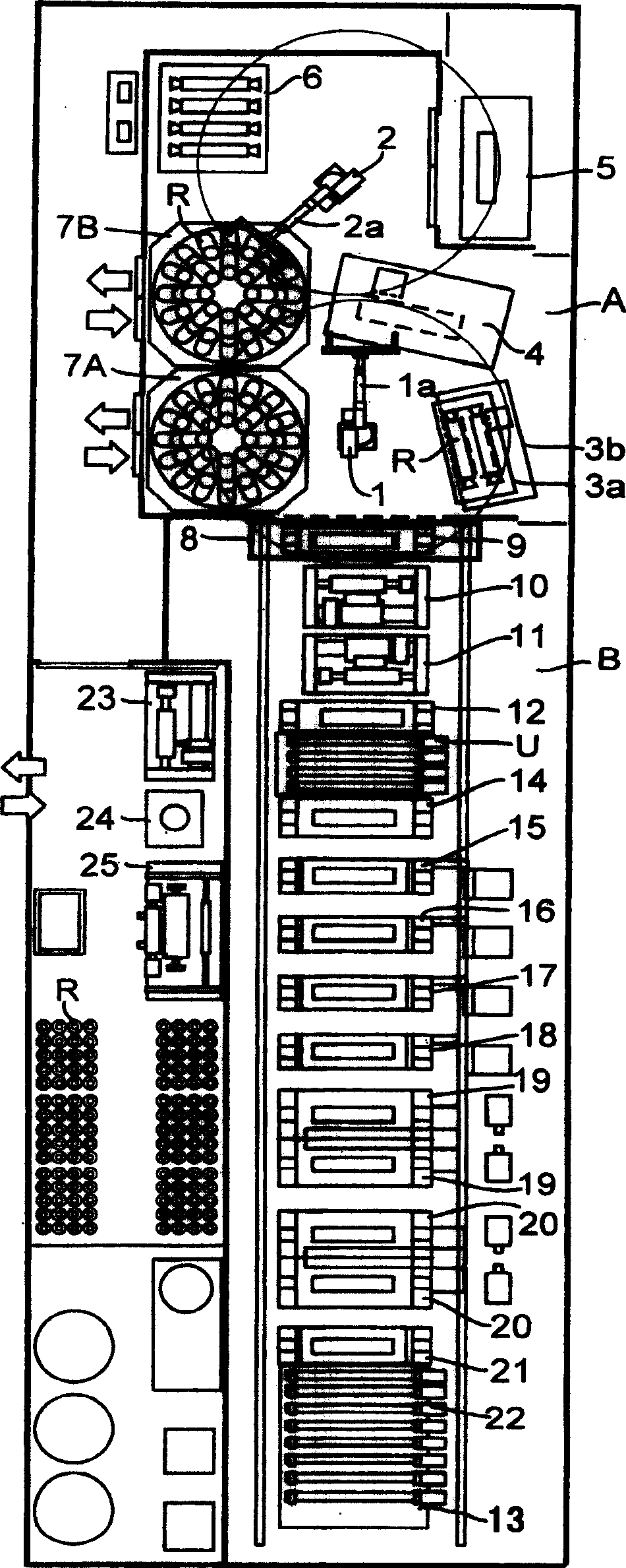
[0196] figure 1 A plan view of a plate making room that is equally applicable to all the plate making methods described above is shown.

[0197] figure 1 The shown equipment configuration shows that for a plate making company that needs various processing steps corresponding to various orders from customers, it is possible to use one production line to cope with all orders. The preferred production line equipment.

[0198] especially in figure 1 In the equipment configuration shown, the chromium plating device is not installed, and instead of it, it becomes a production line equipment that can perform nickel alloy plating, quenching, and heat dissipation and cooling.

[0199] The plate making workshop includes robot room A and electroplating room B.

[0200] On the side near the electroplating chamber B in the robot room A, an industrial robot 1 that can freely reciprocate and rotate is provided. This industrial robot 1 has a robot hand 1a that can clamp both ends of the pl...

Embodiment 2

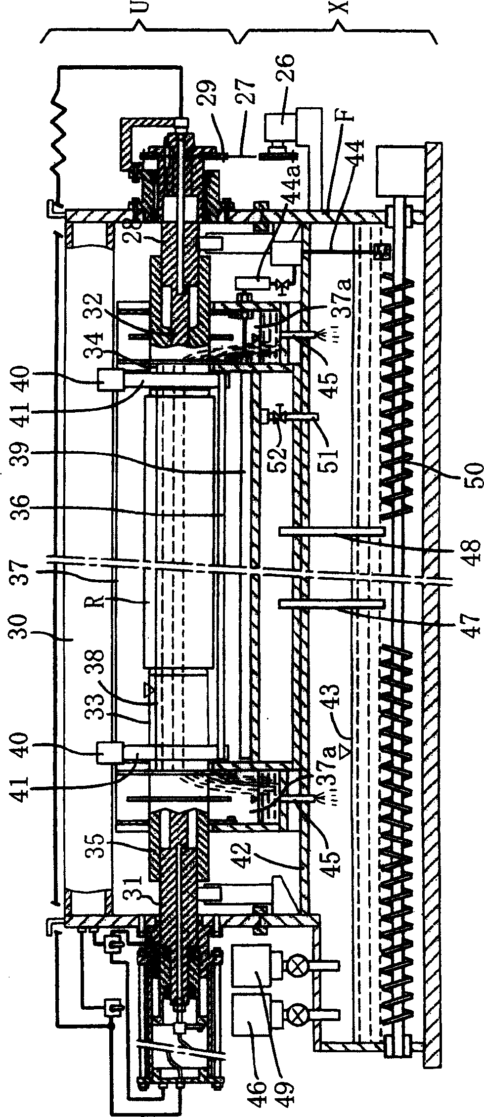
[0213] This example explains in detail an example of copper sulfate electroplating using an insoluble anode constituting a part of a plate making method with reference to the drawings.

[0214] figure 2 Shown is a copper sulfate electroplating device using an insoluble anode that is applicable to a box-shaped roller clamping and turning conveyor that is substantially the same as the box-shaped roller automatic loading and unloading device shown in Japanese Patent Publication No. 57-36995, and is mounted on the electroplating device body X Set the box-shaped roller to clamp the rotary conveying device U for copper sulfate electroplating.

[0215] It will be described in detail below. When the box-shaped rollers are placed on the electroplating apparatus main body X to clamp the rotary conveyor U, the chain 27 of the chain winding device driven by the motor 26 provided on the electroplating apparatus main body X engages the sprocket 29, and the sprocket 29 cooperates with the...

Embodiment 3

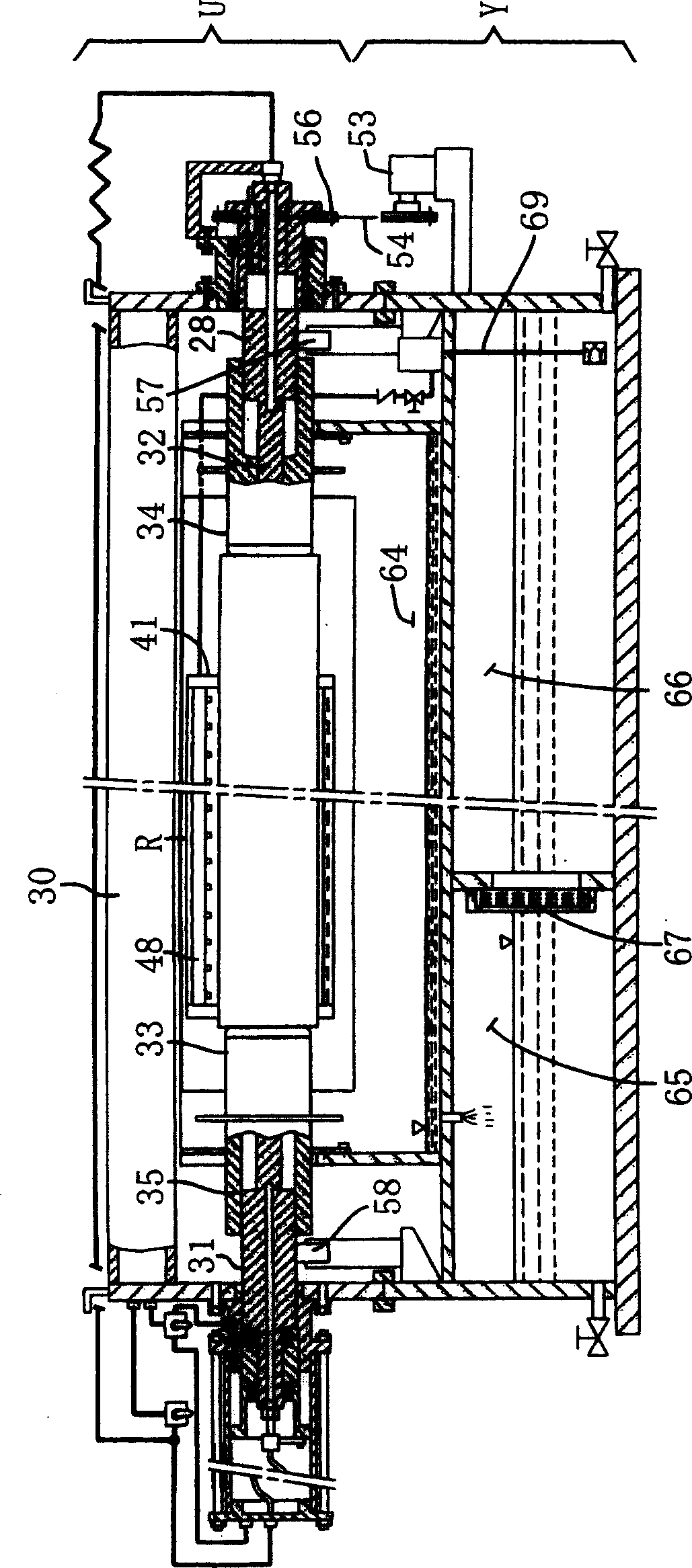
[0233] This embodiment explains in detail, with reference to the drawings, semi-finishing grinding using a liquid-impregnated abrasive-grain-fixed flexible body and mirror-finishing grinding of superfibers without fixed abrasive grains, which constitute a part of the plate making method.

[0234] image 3 A plan view showing a cylindrical polishing device for performing a cylindrical polishing method of an electrolytic polishing method with respect to a plate-making roll for gravure printing of the present invention, Figure 4 A plan view is shown, and FIG. 5 shows a longitudinal side view of main parts.

[0235] The rotary conveyor U is placed on the device body Y with the box-shaped rollers sandwiched between them, and cylindrical grinding is performed. The box-shaped roller clamping and turning conveyance device U has substantially the same configuration as the box-shaped roller automatic attachment and detachment device shown in Japanese Patent Application Publication No....


PUM


Abstract

An electroplating and grinding technology for the plate-making roller before microholes are formed includes such steps as lifting insoluble anode to make it close to lower surface of plate-making roller, supplying the filtered electroplating liquid, electroplating, fixing the liquid-infiltratable abrasive particles and flexible body or superfibres to the surface of grinding head with electrode, supplying electrolyzing liquid, moving the grinding head back and forth along the surface of said roller for electrolytic grinding.

Description

technical field [0001] The present invention relates to a method of electroplating and grinding a plate-making roll before forming micropores, which can form no pits compared with a plate-making roll for gravure printing Copper sulfate plating of uniform thickness and pits, semi-finishing grinding and mirror finishing grinding can be performed in a short time without grinding with a grinding wheel, providing high-quality plate-making rolls. Background technique [0002] Next, two types of plate making methods for a plate-making roll for gravure printing will be described. [0003] (1) In the laser plate-making process of the plate-making roll of the straight plate type, the roll is loaded, ultra-precision cylinder processing is performed by a lathe, and then semi-finishing grinding, finishing grinding, and mirror grinding are performed by a grinding wheel, or in hydrochloric acid. After stripping off chromium and performing cylindrical grinding to correct a perfect circle, ...

Claims


Application Information

Patent Timeline
Patent Type & Authority Applications(China)
IPC IPC(8): B41C1/00
Inventor 井上学祐成和弘松本典子小沼智之重田龙男
Owner THINK LABORATORY CO LTD
Why Eureka
Try Eureka