Plating method and plating bath precursor used therefor

Inactive Publication Date: 2002-06-27
DAIWA FINE CHEM +1
View PDF2 Cites 8 Cited by
  • Summary
  • Abstract
  • Description
  • Claims
  • Application Information

AI Technical Summary

Problems solved by technology

Depending on the form of the object to be plated, since an electric charge is particularly easily concentrated onto a convex portion thereon, the thickness of the plated layer easily becomes uneven.
Depending on the material of the plating metal and the object to be plated, catalysis processing by means of a palladium compound is necessary, and the production cost is high.
Since a reducing agent used for reduction of metal ions accumulates in the bath as oxidized form, and since unnecessary components inevitably contain in the plating bath by supplying a new reducing agent and metal ions to maintain the plating bath which was consumed during the plating, the composition and concentration of the bath easily change, whereby the life of the plating bath is limited.
Since the electroless plating is a metal deposition method using self-catalysis, deposition of a catalyst-poisonous metal is difficult, whereby metal types which can be used for plating are limited.
That is, a redox system plating bath is unstable since it is high in activity of the system reaction as mentioned above, suspended deposition easily occurs, and when such deposition occurs, an even plated layer may not be formed.
Also, the redox system plating bath initially has a fast reaction speed since it has high activity as mentioned above, and this is advantageous in one aspect of the redox system electroless plating method as mentioned above, however, a new problem is caused whereby the life of the plating bath is shortened.
However, as for the latter problem concerning the shorter life of the plating bath, an essential solution has at present not been found.
Therefore, the plating bath is rapidly activated in a short period of time; that is, it loses its reducing power, whereby the life of the plating bath is e

Method used


Image

  • Plating method and plating bath precursor used therefor
  • Plating method and plating bath precursor used therefor
  • Plating method and plating bath precursor used therefor

Examples


example 1

[0135] (Activation Process)

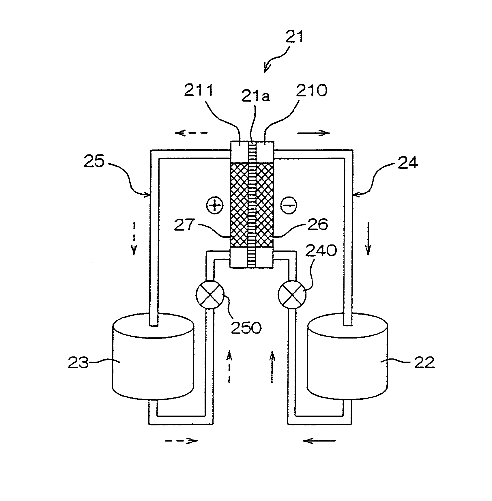
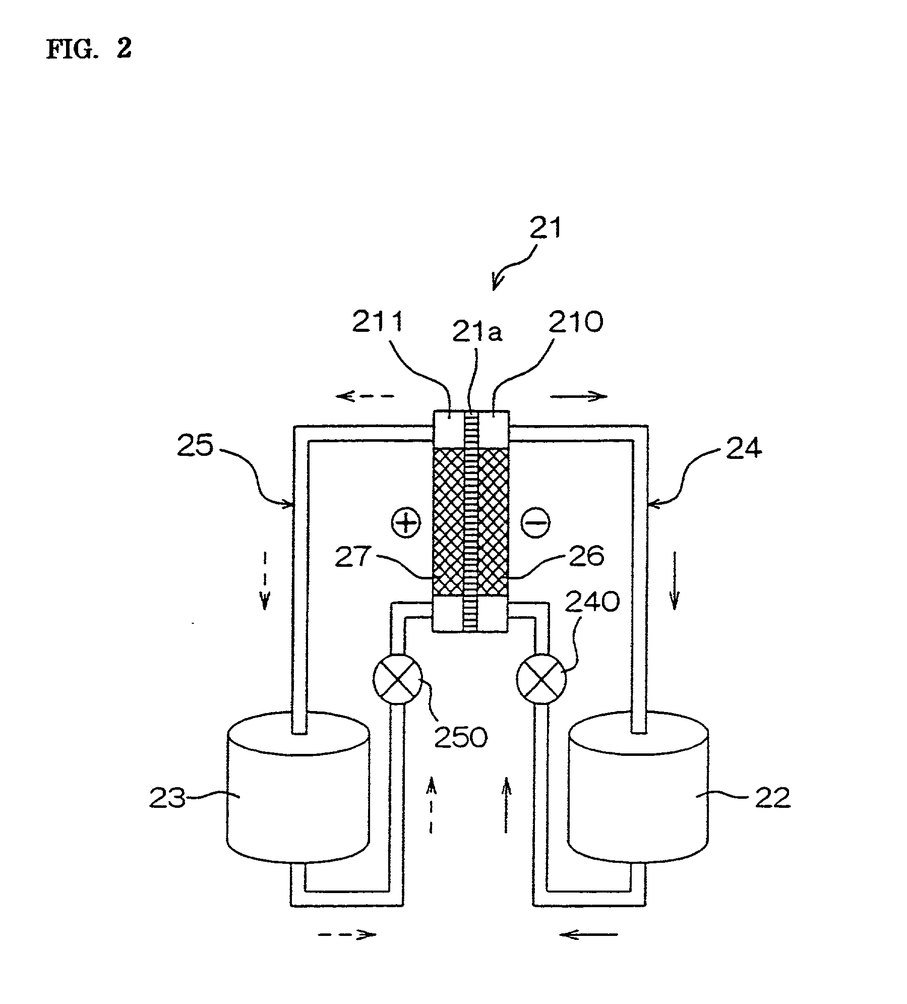
[0136] Hydrochloric acid was added to the nickel plating bath precursor of the abovementioned composition 1 to be adjusted in pH to 1, and then, 1 liter of the bath precursor was poured into each cathode chamber and anode chamber divided by the partition film in the preparation tank for activation, and activation processing was carried out by supplying the electrical current under the following conditions:

[0137] Cathode: Platinum-coated titanium plate

[0138] Anode: Platinum-coated titanium plate Current density at the cathode: 15A / dm.sup.2

[0139] Processing time: 2 hours

[0140] Bath temperature: 25.degree. C.

[0141] (Plating Process)

[0142] 2 liters in total of the plating bath processed by the abovementioned activation process in cathode and anode chambers were poured into the plating tank, and added with ammonia to be adjusted in pH to 8.

[0143] Thereafter, while maintaining the dipping temperature at 40.degree. C., an ABS resin plate which was treated with pa...

example 3

[0146] The nickel plating bath of the abovementioned composition 2 was prepared, poured in a beaker, left for an entire day and night, and then 2 liters of the bath were poured into the plating tank, into which an ABS resin plate treated with palladium catalysis was dipped for 10 minutes while maintaining the dipping temperature at 40.degree. C. However, a nickel plated layer was not formed on the surface, and it was confirmed that the plating bath had lost activity.

[0147] Therefore, hydrochloric acid to be adjusted in pH to 1 was added to this plating bath, and then 1 liter of the bath was poured into each cathode chamber and anode chamber which were divided by the partition film in the preparation tank for activation, and applied with activation processing under the same conditions as in the above Example 1.

[0148] And, when 2 liters in total of the processed plating baths in the cathode and anode chambers were poured into the plating tank and mixed, added with ammonia to be adjust...

example 4

[0149] The plating bath which was applied with nickel plating processing in the above Example 1 was recovered, and added with hydrochloric acid to be adjusted in pH to 1. Then, 1 liter of the bath was poured into each cathode chamber and anode chamber divided by the partition film in the preparation tank for activation again, and activated under the same conditions as in the above Example 1. However, in this case, a nickel electrode plate was used as the anode.

[0150] Then, when 2 liters in total of the plating baths in the cathode and anode chambers were poured into the plating tank, adjusted in pH to 8 with the addition of ammonia, and an ABS resin plate treated with palladium catalysis was dipped in the bath for 10 minutes while maintaining the dipping temperature at 40.degree. C., it was confirmed that a nickel plated layer with a thickness of approximately 0.6 .mu.m was formed.

[0151] Also, when the plating bath after being applied with nickel plating processing in the above Exam...


PUM

PropertyMeasurementUnit
Lengthaaaaaaaaaa
Dissociation constantaaaaaaaaaa
Fractionaaaaaaaaaa

Abstract

To provide a plating method, which enables wide industrial use of the redox system electroless plating method having excellent characteristics, and a plating bath precursor which is preferable for the plating method. The plating method comprises a process oxidizing first metal ions of a redox system of a plating bath from a lower oxidation state to a high oxidation state, and second metal ions of said redox system are reduced and deposited onto the surface of an object to be plated, wherein a process is provided in which by supplying the electrical current to the plating bath, the first metal ions are reduced from said lower oxidation state to thereby activate the plating bath. The plating bath precursor is formed stabilizing the plating bath so that reduction and deposition of the second metal ions substantially do not occur in order to improve its storing performance.

Description

BACKGROUND OF THE INVENTION 1. Field of the Invention[0001] The present invention relates to a new plating method and a plating bath precursor to be used therefor.[0002] 2. Description of the Related Art[0003] A wet plating method for reducing metal ions in a bath and depositing the ions onto the surface of an object to be plated is classified roughly into an electroplating (electrolyzing deposition) method and an electroless plating (chemical deposition) method on the basis of the reduction mechanism as generally known. Both methods have merits and demerits.[0004] For example, the electroplating method has advantages whereby, during plating, metal ions of basically the same amount as that of the metal deposited on the surface of the object to be plated are supplied from the anode, and the composition of a plating bath is maintained roughly constant, and therefore, said plating bath can be continuously used over a long period of time, however, it also has the following problems:[000...

Claims


Application Information

Patent Timeline
IPC IPC(8): C23C18/31C23C18/16C23C18/34
CPCC23C18/34Y10T428/12896Y10S428/935Y10T428/12819Y10T428/12889Y10T428/12903Y10T428/12875Y10T428/12861Y10T428/12701Y10T428/12944Y10T428/12708Y10T428/12792Y10T428/12826Y10T428/12951Y10T428/12847Y10T428/12681C23C18/1617
Inventor OBATA, KEIGOKIM, DONG-HYUNTAKEUCHI, TAKAONAKAO, SEIICHIROINAZAWA, SHINJIKARIYA, AYAOMAJIMA, MASATOSHINAKAYAMA, SHIGEYOSHI
Owner DAIWA FINE CHEM
Why Eureka
Try Eureka