Cabling mechanism of frame-type strander

A technology of frame stranding machine and cable routing hole, which is applied in the field of frame stranding machine, which can solve the problems of wearing, setting, winding, and damaging the surface of cables, etc., and achieve the effect of avoiding detachment and inclination

Inactive Publication Date: 2020-05-01
NANTONG HONGFENG ELECTRO MECHANIC
View PDF1 Cites 2 Cited by
  • Summary
  • Abstract
  • Description
  • Claims
  • Application Information

AI Technical Summary

Problems solved by technology

[0003] In order to overcome the existing problems in the prior art, the excessive friction between the cable and the frame stranding machine leads to damage to the surface of the cable and the slackness of the cable leads to mutual wear and entanglement, the present invention provides a wire routing mechanism for the frame stranding machine

Method used


Image

  • Cabling mechanism of frame-type strander

Examples


Embodiment Construction

[0017] The present invention will be described in further detail below in conjunction with the accompanying drawings and embodiments. It should be understood that the specific embodiments described here are only used to explain the present invention, not to limit the present invention.

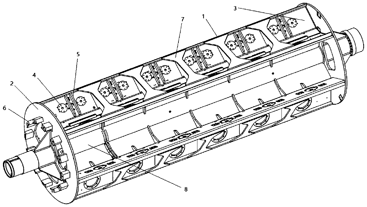
[0018] The invention discloses a wire routing mechanism of a frame stranding machine, such as figure 1 As shown: it includes a rotating reel 1, a winding reel, and a twisting reel 2. Cables are wound on the reel, and several wire pulleys 4 are arranged in the wire separation area 3 of the rotating reel 1. A wire management plate 5 is provided between the guide wheels 4, and a wiring hole 6 is provided on the twisting reel 2, and the wiring hole 6 is square, and a clamping mechanism is provided in the wiring hole 6; The above-mentioned cables pass through the guide wheel 4 and the cable management plate 5 from the winding reel to enter the cable hole 6; each cable from the winding reel passes ...


PUM


Abstract

The invention provides a cabling mechanism of a frame-type strander. The mechanism comprises a rotary pay-off cylinder, a wire spool and a wire twisting disc, and is characterized in that a cable is wound on the wire spool, a plurality of wire guide wheels are arranged in a wire separation area of the rotary pay-off cylinder, wire arranging plates are arranged among the wire guide wheels, a squarecabling hole is formed in the wire twisting disc, and a wire clamping mechanism is arranged in the cabling hole; the cable goes out of the wire spool, passes through the wire guide wheel and the wirearranging plate in sequence and enters the cabling hole; sliding friction of cables of a traditional structure is changed into rolling friction, the transmission resistance of the cables is reduced,abrasion of the surfaces of the cables is reduced, the cables are arranged in order through the arrangement of the cable arranging plate, and the phenomena of disengagement and inclination in the transmission process are avoided.

Description

technical field [0001] The invention belongs to the technical field of frame stranding machines, and relates to a wire routing mechanism, in particular to a wire routing mechanism of a frame stranding machine. Background technique [0002] In the existing wire routing mechanism of the frame stranding machine, partitions are arranged between the horizontally adjacent winding disks, and each partition is opened with a wire mold hole, and the cables on the winding disk pass through the passages on each partition. The wire die holes converge to the twisting reel, and there are also wire die holes distributed on the circumference of the twisting reel. Guide wheel, the cable is routed through the guide wheel. During the specific working process, the cable passes through multiple wire-passing die holes, which is severely worn, and when passing through the front support seat, when the distributed cables go When pulling the wire, it will rub against the edge of the guide wheel and c...

Claims


Application Information

Patent Timeline
Patent Type & Authority Applications(China)
IPC IPC(8): H01B13/02
CPCH01B13/0207
Inventor 王艳峰
Owner NANTONG HONGFENG ELECTRO MECHANIC
Why Eureka
Try Eureka