Wafer tray marking method and structure thereof

A disk structure and wafer technology, applied in laser welding equipment, electrical components, circuits, etc., can solve the problems of high temperature of baking, separation of wafer holder, user troubles, etc.

Inactive Publication Date: 2020-05-01
王智
View PDF5 Cites 0 Cited by
  • Summary
  • Abstract
  • Description
  • Claims
  • Application Information

AI Technical Summary

Problems solved by technology

[0004] The known marking method is to affix a label for identification on one side of the wafer holder. However, the wafer undergoes baking and cleaning processes in the packaging process at the same time during the packaging process, and is continuously repeated. us

Method used


Image

  • Wafer tray marking method and structure thereof
  • Wafer tray marking method and structure thereof
  • Wafer tray marking method and structure thereof

Examples


Embodiment Construction

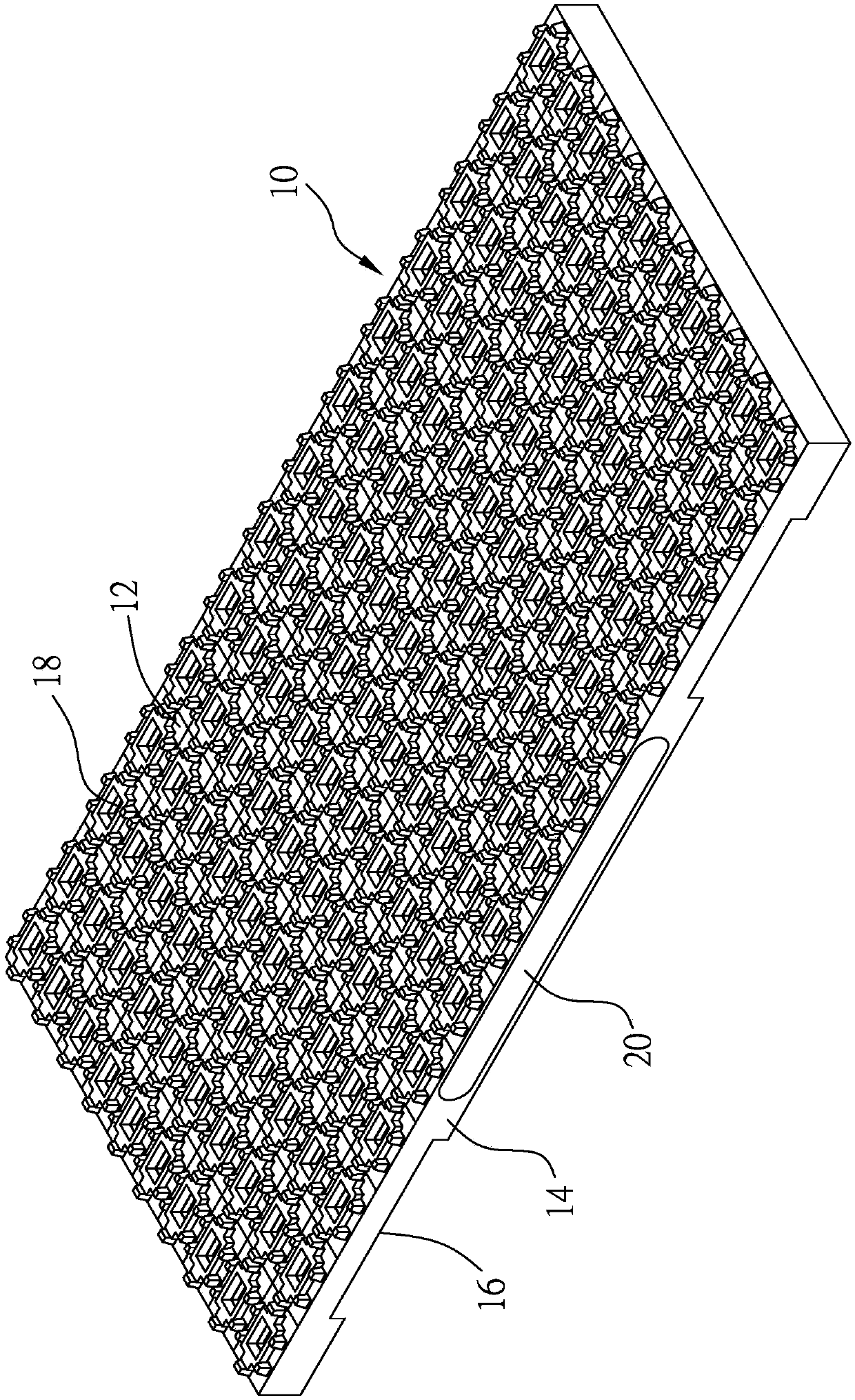
[0027] see figure 1 , is a wafer chuck structure provided by a preferred embodiment of the present invention, which includes a chuck body 10 and a coating layer 20 .

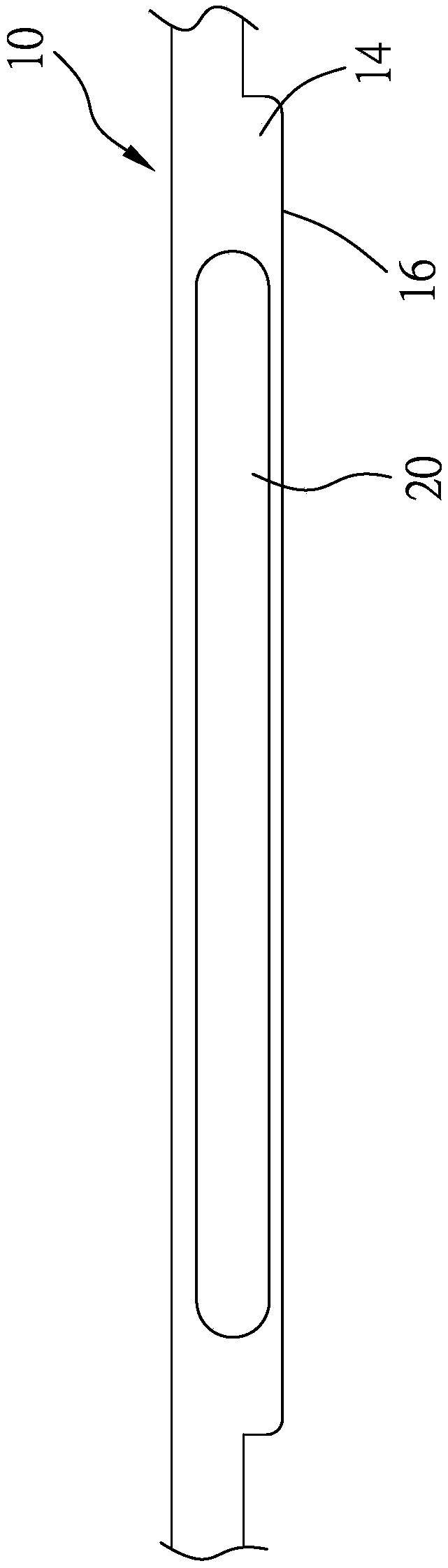
[0028] The support plate body 10 is a rectangular plate shape. The support plate body 10 has a bearing surface 12, a peripheral surface 14 and a bottom surface 16. The bearing surface 12 is opposite to the bottom surface 16. The peripheral surface 14 is located between the bearing surface 12 and the bottom surface 16 Between the bottom surface 16 and the peripheral surface 14 connects the carrying surface 12 and the bottom surface 16 . The tray body 10 further has a bearing portion 18 formed on the bearing surface 12 and extending toward the bottom surface 16 .

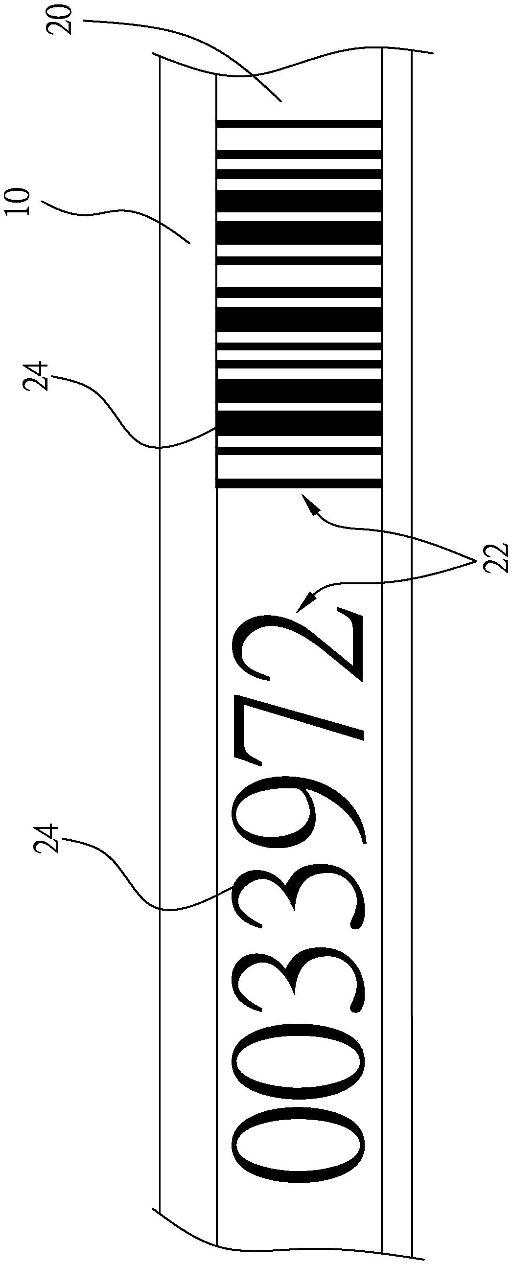
[0029] see figure 2 , the coating layer 20 is disposed on the peripheral surface 14 or the bottom surface 16 of the susceptor body 10 . In this embodiment, the coating layer 20 may be disposed on the peripheral surface 14 of the susceptor body 10 by...


PUM


Abstract

The invention relates to a forming method of a wafer tray mark. The method comprises steps that a forming step is performed, a tray body is formed by using plastic, one side of the tray body is a bearing surface, the other side of the tray body is a bottom surface, a peripheral surface is positioned between the bearing surface and the bottom surface, and the peripheral surface is connected with the bearing surface and the bottom surface; a coating step is performed, a coating layer is arranged on the peripheral surface or the bottom surface of the bearing plate body, and the color of the coating layer is different from that of the bearing plate body. A mark structure is a combination of a plurality of hollowed-out parts, the hollowed-out parts are formed on the coating layer, and the colorof a surface of the bearing plate body can be transmitted out of the hollowed-out parts, so the mark structure composed of the hollowed-out parts is visible and/or scannable.

Description

technical field [0001] The invention relates to a marking forming method, in particular to a marking forming method of a wafer carrier. Background technique [0002] With the development of high-tech manufacturing industry, most of the wafers are transported by automatic conveying system during transportation. In the manufacturing process or handling process of the wafer, the wafer is usually accommodated in a slot of a susceptor, and the susceptor is used to prevent the wafer from being damaged due to external impact. [0003] In the case of mass production of wafers, hundreds or even more chucks are required to carry the wafers, and in order to distinguish wafers that have passed through different processes, the user needs to use such a large number of chucks. Relevant detailed information about the manufacturing process is marked one by one on the carrier carrying the wafer. [0004] The known marking method is to affix a label for identification on one side of the wafe...

Claims


Application Information

Patent Timeline
IPC IPC(8): H01L21/683H01L21/687B23K26/362
CPCH01L21/68714H01L21/68757H01L21/683B23K26/362
Inventor 王智
Owner 王智
Why Eureka
Try Eureka