U-shaped driver

A driver, U-shaped technology, applied in the direction of electromechanical devices, electrical components, etc., can solve the problems of non-renewable, fossil energy pollution, etc.

Pending Publication Date: 2020-05-01
叶景荣
View PDF0 Cites 0 Cited by
  • Summary
  • Abstract
  • Description
  • Claims
  • Application Information

AI Technical Summary

Problems solved by technology

[0003] The purpose of the present invention is to solve the non-renewable problem of fossil energy pollution in the prior art, and propose a U-shaped driver

Method used


Image

  • U-shaped driver
  • U-shaped driver
  • U-shaped driver

Examples


Embodiment Construction

[0025] The following will clearly and completely describe the technical solutions in the embodiments of the present invention with reference to the accompanying drawings in the embodiments of the present invention. Obviously, the described embodiments are only some, not all, embodiments of the present invention.

[0026] In describing the present invention, it should be understood that the terms "upper", "lower", "front", "rear", "left", "right", "top", "bottom", "inner", " The orientation or positional relationship indicated by "outside", etc. is based on the orientation or positional relationship shown in the drawings, and is only for the convenience of describing the present invention and simplifying the description, rather than indicating or implying that the referred device or element must have a specific orientation, so as to Specific orientation configurations and operations, therefore, are not to be construed as limitations on the invention. In addition, the terms "fir...


PUM


Abstract

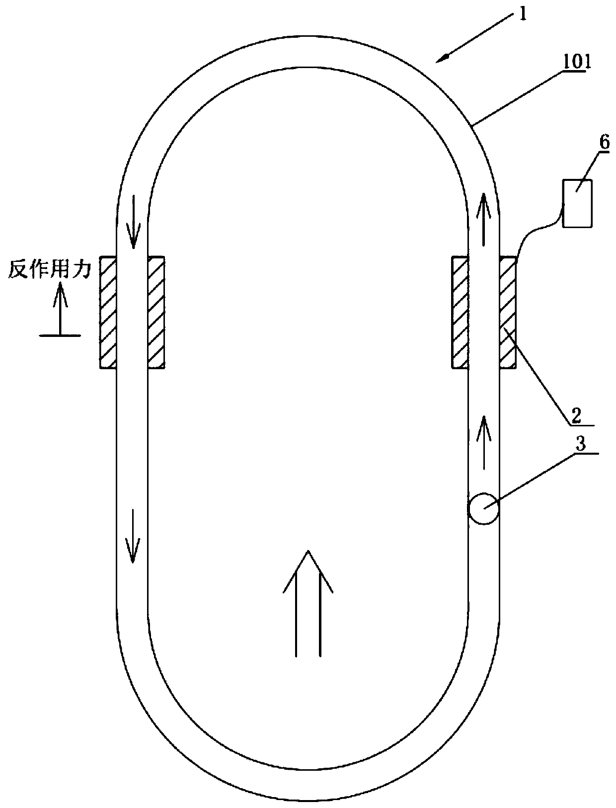
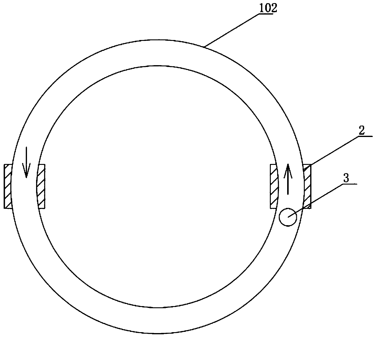
The invention discloses a U-shaped driver and belongs to the field of a driver. The U-shaped driver comprises a pipe ring, electromagnetic driving devices and a rotor, wherein the electromagnetic driving devices are symmetrically arranged on two sides of the pipe ring, the rotor is arranged in the pipe ring, and the electromagnetic driving devices are used for providing power for the rotor to do circular motion. The driver is simple in structure and convenient to use, the rotor does circular motion in the pipe ring, high-efficiency cyclic utilization can be achieved, internal acting is adoptedfor direct driving, compared with traditional reciprocating acting, indirect driving and material throwing driving, efficiency is improved by many times, by means of the device, turning, advancing, retreating and hovering of the driver can be achieved, the driver can be installed outside or inside an aircraft cabin, a plurality of devices can move in any track and space through cooperative use, the driver can further be used as a backpack for flying of people to be installed on an intelligent robot, and free displacement of the intelligent robot is achieved.

Description

technical field [0001] The invention relates to the technical field of U-shaped drives, in particular to a U-shaped drive. Background technique [0002] Today's human living environment is relatively severe, and the important atmospheric environment is a very important aspect. The air pollution caused by the exhaust gas generated by fuel combustion has ranked first in the pollution sources. In the item of fuel, the exhaust gas of power combustion also accounts for a very large proportion. In the existing traditional science, there is such a dynamic model possible. So far, traditional driving methods and resources cannot meet human needs, so it is urgent to design a clean energy source to ensure sustainable development. Magnetic power as a clean energy source has been put on the research agenda. Contents of the invention [0003] The purpose of the present invention is to solve the problem that the fossil energy pollutes the environment and cannot be regenerated in the p...

Claims


Application Information

Patent Timeline
Patent Type & Authority Applications(China)
IPC IPC(8): H02K53/00
CPCH02K53/00
Inventor 叶景荣
Owner 叶景荣
Why Eureka
Try Eureka