
A long-distance transmission device for electromagnetic signals with large dynamic range

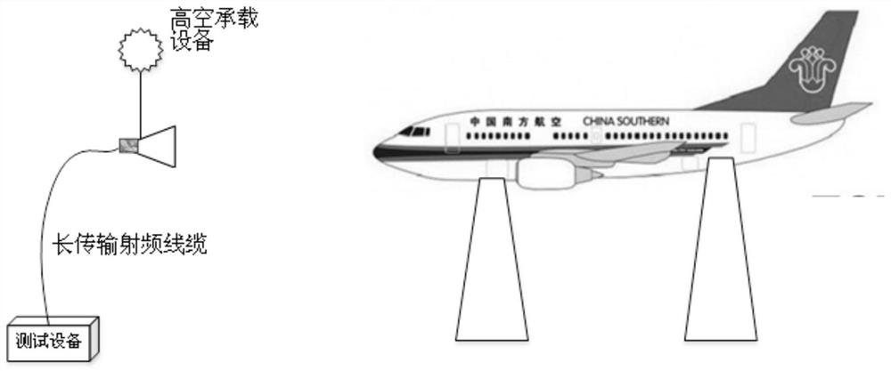
A technology with a large dynamic range and electromagnetic signals, which is applied in the transmission system, electrical components, etc., can solve the problems of high-altitude electromagnetic characteristic testing that have not been popularized, high-altitude loads are too heavy, and there is no standard test configuration. Layout difficulty and personnel requirements, accurate identification, and the effect of reducing the total cost of the test

Active Publication Date: 2021-06-29
广电计量检测(西安)有限公司 +1
View PDF8 Cites 0 Cited by
  • Summary
  • Abstract
  • Description
  • Claims
  • Application Information

AI Technical Summary

Problems solved by technology

Because the use of battery power supply will cause the problem of overloading the high-altitude load; the use of power supply with special wires to transmit to the preamplifier will cause the wires and RF cables to form twists in the air, which poses a serious safety risk and will also cause additional damage. load
[0004] For this problem, since it mainly exists in the performance research and testing of military aircraft / civil aircraft or ship superstructure, the current relevant test standards do not have a standard test configuration that can be followed, and the industry has not promoted a set of practical ones. Test method to solve the practical difficulties encountered in the high-altitude electromagnetic characteristic test

Method used


Image

  • A long-distance transmission device for electromagnetic signals with large dynamic range
  • A long-distance transmission device for electromagnetic signals with large dynamic range
  • A long-distance transmission device for electromagnetic signals with large dynamic range

Examples


Embodiment Construction

[0045]The following will clearly and completely describe the technical solutions in the embodiments of the present invention with reference to the accompanying drawings in the embodiments of the present invention. Obviously, the described embodiments are only some, not all, embodiments of the present invention. Based on the embodiments of the present invention, all other embodiments obtained by persons of ordinary skill in the art without creative efforts fall within the protection scope of the present invention.

[0046] The terms "comprising" and "comprising" indicate the presence of described features, integers, steps, operations, elements and / or components, but do not exclude the presence of one or more other features, integers, steps, operations, elements, components and / or The presence or addition of its collection.

[0047] The term "and / or" refers to any combination of one or more of the associated listed items and all possible combinations, and includes such combinati...


PUM


Abstract

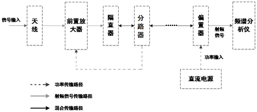
An embodiment of the present invention provides a long-distance transmission device for electromagnetic signals with a large dynamic range, including: a preamplifier, a DC blocker, a splitter, and a biaser; The signal is amplified to reduce the background noise of the system; the biaser is used to realize the combination of the direct current and the signal, so that the direct current and the signal are transmitted through the same axial cable; the biaser is also used to ensure that the direct current will not Enter the spectrum analyzer and provide high impedance for the DC power supply to ensure that the signal is not injected into the DC power input; the splitter is used to separate the total path signal from the DC, and at the same time provide high impedance to ensure that the signal does not enter the front The power supply end of the preamplifier; the DC blocker is used to ensure that direct current will not enter the signal input end of the preamplifier. The embodiments of the present invention can accurately identify tiny electromagnetic signals during the long-distance transmission test of electromagnetic signals.

Description

technical field [0001] The invention relates to the technical field of communication electronics, in particular to a long-distance transmission device for electromagnetic signals with a large dynamic range. Background technique [0002] When testing the electromagnetic characteristics of large-scale equipment such as an entire aircraft, in order to obtain a good electromagnetic background noise in the absence of a fully anechoic chamber that meets the test conditions, it is generally selected in a remote location with relatively few surrounding power and electronic facilities. place. The traditional test method transmits the radio frequency signal received by the antenna to the test equipment through a coaxial low-loss cable, and then uses signal processing technology to perform a series of transformations, so as to realize the monitoring of time domain signals to frequency domain signals. However, this traditional method has disadvantages such as large signal transmission ...

Claims


Application Information

Patent Timeline
Patent Type & Authority Patents(China)
IPC IPC(8): H04B1/16H04B1/10
CPCH04B1/1018H04B1/16
Inventor 付喆
Owner 广电计量检测(西安)有限公司
Learn More