
Alarm device special for power equipment

A technology for warning devices and power equipment, applied to display devices, lighting devices, circuit layout, etc., can solve problems such as danger of power equipment, difficulty in noticing warning signs, waste of time and energy, etc., to avoid danger and ensure normal display , saving time and energy

Inactive Publication Date: 2020-05-05
李建科
View PDF6 Cites 4 Cited by
  • Summary
  • Abstract
  • Description
  • Claims
  • Application Information

AI Technical Summary

Problems solved by technology

[0003] 1. Since the warning sign is exposed to the outdoors for a long time, a large amount of dust is easy to accumulate on the warning sign after a period of time. The dust attached to the warning sign will affect people's ability to see the slogan on the warning sign. Therefore, it is necessary to regularly clean the warning sign. , if the dust is manually removed, the staff needs to use a rag to wipe off the dust on the warning sign, which wastes a lot of time and energy;
[0004] 2. At night, due to the dim light, it is difficult for people to notice the warning signs. Therefore, it is easy to cause people to touch the electrical equipment and cause danger or damage the electrical equipment because they fail to notice the warning signs.

Method used


Image

  • Alarm device special for power equipment
  • Alarm device special for power equipment
  • Alarm device special for power equipment

Examples


Embodiment Construction

[0022] The following will clearly and completely describe the technical solutions in the embodiments of the present invention with reference to the accompanying drawings in the embodiments of the present invention. Obviously, the described embodiments are only some, not all, embodiments of the present invention.

[0023] In describing the present invention, it should be understood that the terms "upper", "lower", "front", "rear", "left", "right", "top", "bottom", "inner", " The orientation or positional relationship indicated by "outside", etc. is based on the orientation or positional relationship shown in the drawings, and is only for the convenience of describing the present invention and simplifying the description, rather than indicating or implying that the referred device or element must have a specific orientation, so as to Specific orientation configurations and operations, therefore, are not to be construed as limitations on the invention.

[0024] refer to Figure ...


PUM


Abstract

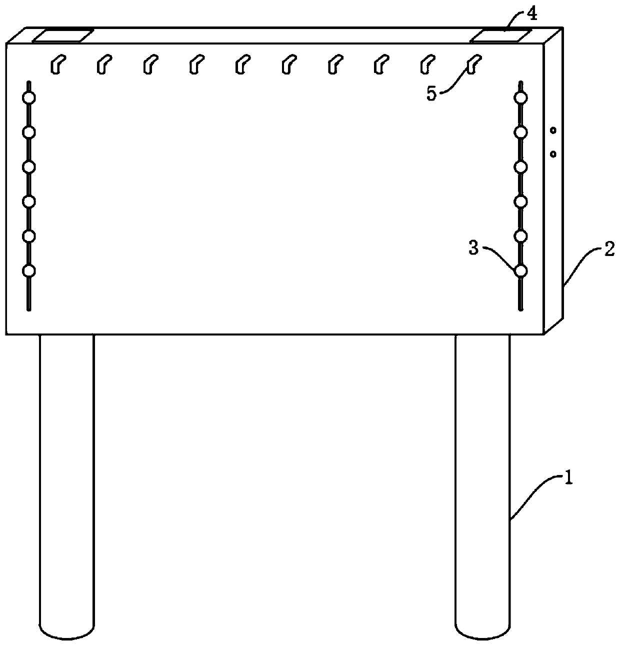
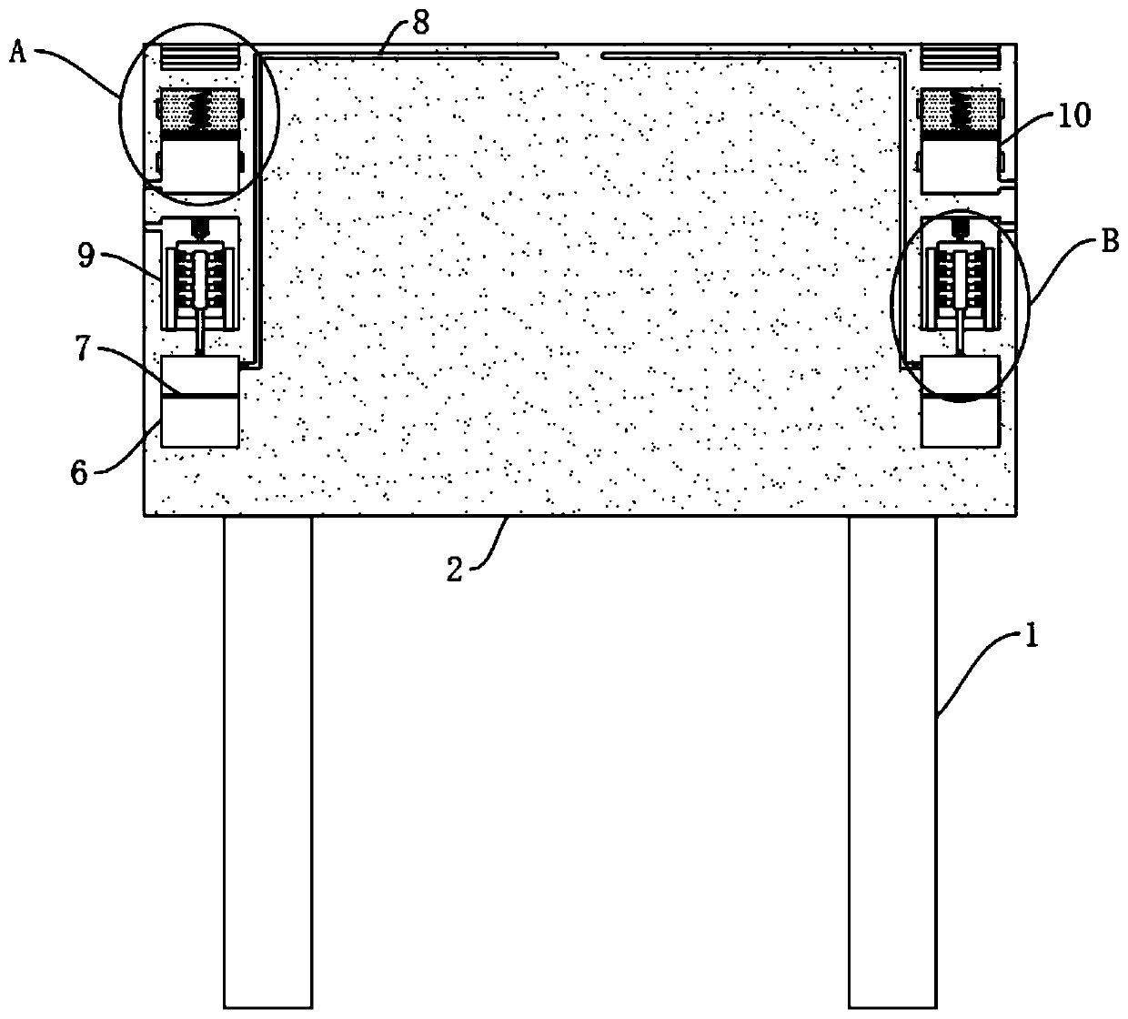
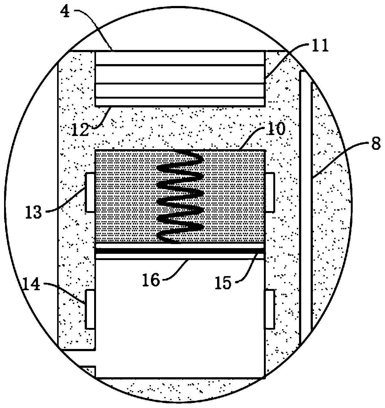
The invention discloses an alarm device special for power equipment. The alarm device special for the power equipment comprises two supporting rods; the upper ends of the two supporting rods are commonly and fixedly connected with an alarm plate; a power supply mechanism is arranged on the upper wall of the alarm plate; a control mechanism is arranged in the alarm plate; the control mechanism comprises a control cavity formed in the alarm plate; the upper wall of the control cavity is elastically connected with a control panel through a tension spring; the space, positioned in the upper end ofthe control panel, of the control cavity is filled with a medium capable of expanding by heat and retracting by cold; two first electricity conducting plates are fixedly arranged on the side walls, close to the upper end, of the control cavity in an embedded manner; two second electricity conducting plates are fixedly arranged on the side walls, close to the lower end, of the control cavity in the embedded manner; an electricity conducting rod is arranged in the control panel in a penetrating manner; and an air spraying mechanism is arranged in the alarm plate. According to the alarm device special for the power equipment, normal display of the information on the alarm plate can be ensured; the time and energy of people are greatly saved; and the danger of people caused by being in contact with the power equipment because of dark light can also be avoided.

Description

technical field [0001] The invention relates to the technical field of electric equipment, in particular to a special warning device for electric equipment. Background technique [0002] Nowadays, the use of electric equipment is more and more extensive. There are many electric equipment outdoors, and these electric equipment are generally expensive and easy to cause danger. Therefore, people usually set up warning signs around these electric equipment to warn people. , to remind people to pay attention to the electrical equipment, to prevent people from being accidentally injured or damaged by the electrical equipment, but the existing warning signs have the following problems: [0003] 1. Since the warning sign is exposed outdoors for a long time, a large amount of dust is easy to accumulate on the warning sign after a period of time. The dust attached to the warning sign will affect people's ability to see the slogan on the warning sign. Therefore, it is necessary to regu...

Claims


Application Information

Patent Timeline
IPC IPC(8): B08B5/02F21S9/03F21V23/04G09F7/18G09F13/00
CPCB08B5/02F21S9/03F21V23/04G09F7/18G09F13/00
Inventor 李建科刘红亮
Owner 李建科
Learn More