All-solid-state holographic projector

A projector, all-solid-state technology, applied in the field of 3D display, can solve the problems of complex computing and control system, high manufacturing cost, and extremely high screen refresh speed requirements, so as to improve reliability and image quality, protect eyesight, and reduce production costs. and the effect of controlling difficulty

Pending Publication Date: 2020-05-05
JINGMEN CITY DREAM EXPLORATION TECH CO LTD
View PDF3 Cites 18 Cited by
  • Summary
  • Abstract
  • Description
  • Claims
  • Application Information

AI Technical Summary

Problems solved by technology

Although this method can realize the projection of 3D images, due to the existence of scanning moving parts, the reliability of the system cannot be guaranteed, and the requirements for the refresh rate of the images are extremely high, which makes the calculation and control system extremely complicated, and it is difficult to achieve stable The screen shows that the manufacturing cost is extremely high

Method used


Image

  • All-solid-state holographic projector
  • All-solid-state holographic projector
  • All-solid-state holographic projector

Examples


Embodiment 1

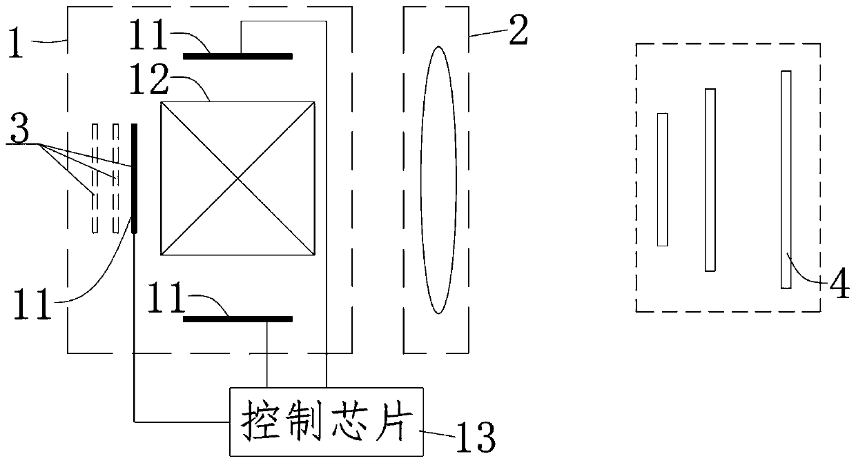
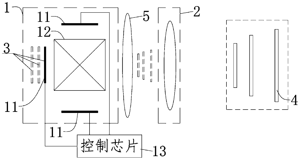
[0068] The number of projection units 11 is 2, and the image plane integration mirror group 12 is a hexahedral X-combining prism, which is spliced ​​by 4 prism mirrors whose cross-section is an isosceles right-angled triangle, and the cross-section is a square. The interior of the X-combining prism A semi-transparent and semi-reflective film is provided at the splicing seam, and the two projection units 11 are respectively located on the two opposite sides of the X-combining prism, which are perpendicular to the cross-section of the outer surface, and the two projection units 11 are located at a corresponding distance from the X-combining prism. One of the other two outer surfaces of the X-combining prism perpendicular to its cross-section is the exit surface, and the exit surface faces the projection lens group 2. The actual effect is as if there are two parallel equivalent image planes 3 arranged behind the exit surface. After the two parallel equivalent image planes 3 are di...

Embodiment 2

[0071] The number of projection units 11 is 3, and the image plane integration mirror group 12 is a hexahedral X-combining prism which is spliced ​​by 4 prisms whose cross-section is an isosceles right-angled triangle, and the cross-section is a square, and the X-combining prism is assembled internally The slit is provided with a semi-transparent and semi-reflective film, and the three projection units 11 are respectively located on one side of the three outer surfaces of the X-combining prism perpendicular to its cross-section, and the distances between the three projection units 11 and the corresponding side surfaces of the X-combining prism are respectively Not the same, the fourth outer surface of the X-combining prism perpendicular to its cross section is the exit surface, and the exit surface faces the projection lens group 2 . In actual effect, it is as if there are three parallel equivalent image planes 3 arranged behind the exit surface. After the three parallel equiva...

Embodiment 3

[0073] The number of projection units 11 is 5, and the image plane integration mirror group 12 is a cube prism composed of several sub-prisms, and the sub-prism is composed of any surface of a cube, taking two adjacent vertices and face centers and the geometric center of the cube , a tetrahedral prism composed of four points, a semi-transparent and semi-reflective film is provided at the joint joints inside the cube prism, and the five projection units 11 are respectively facing the five faces of the cube prism, and the distances from each surface are different. The sixth surface of the cube prism is the outgoing surface, and the outgoing surface faces the projection lens group 2 . In actual effect, it is as if there are five parallel equivalent image planes 3 arranged behind the exit surface. After the five parallel equivalent image planes 3 are directly transformed by the optical path of the projection lens group 2, they are respectively formed in space with the five paralle...


PUM


Abstract

The invention relates to the field of 3D display, and discloses an all-solid-state holographic projector, which comprises an imaging module and a projection lens group arranged in the holographic projector, wherein the imaging module is used for providing a plurality of equivalent image surfaces which are not overlapped or are parallel to one another, a distance between any two adjacent equivalentimage surfaces is L(mm), the distance between adjacent pixels on a single equivalent image surface is d (mm), and L is greater than or equal to 2d; and the projection lens group is used for projecting the image surface group formed by the imaging module to form a 3D projection picture of depth information in space. A real 3D image projection function is realized by introducing a scheme of a plurality of equivalent image surfaces. Because the equivalent image surface is distributed at different depths in the space, the projected picture is also provided with depth information, and the real 3Ddisplay content can be provided for the user by matching with the holographic screen. The moving parts are not needed in the working process, the reliability and the image quality are greatly improved, and meanwhile the production cost and the control difficulty are reduced.

Description

technical field [0001] The invention relates to the field of 3D display, in particular to an all-solid-state holographic projector. Background technique [0002] 3D display technology can provide additional depth information on the basis of traditional two-dimensional display, so it is considered to be the development direction of next-generation display technology. However, there is no effective solution for realizing 3D display at present, and most of the commercially successful cases are pseudo-3D technologies based on stereoscopic image pairs, which cannot provide users with real 3D images with depth information. For example, the principle of 3D movies in cinemas is to use a projector to project two two-dimensional left and right eye image pairs on the screen. By wearing selective filter eyes, the two eyes receive different images, thus creating a kind of Seeing the illusion of a 3D image, but in fact the projected image is only a 2D image. Prolonged viewing can also c...

Claims


Application Information

Patent Timeline
Patent Type & Authority Applications(China)
IPC IPC(8): G09F19/18G03B35/18
CPCG09F19/18G03B35/18
Inventor 王广军余为伟
Owner JINGMEN CITY DREAM EXPLORATION TECH CO LTD
Why Eureka
Try Eureka