Connector Assemblies and Plugs

A connector and cable connector technology, which is applied in the direction of connection, parts of connecting devices, two-part connecting devices, etc., can solve the problems of time-consuming and labor-intensive protective sleeves, easy torn, etc.

Active Publication Date: 2021-07-30
CHINA AVIATION OPTICAL-ELECTRICAL TECH CO LTD
View PDF5 Cites 0 Cited by
  • Summary
  • Abstract
  • Description
  • Claims
  • Application Information

AI Technical Summary

Problems solved by technology

[0006] The purpose of the present invention is to provide a plug to solve the problem of time-consuming and labor-intensive assembly of the plug and the double-sheathed cable in the prior art and the protection sheath is easy to tear. Another purpose of the present invention is to provide a connector assembly, It is used to solve the problem of time-consuming and labor-intensive assembly of the connector assembly and the double-sheathed cable in the prior art and the problem that the protective sheath is easy to tear

Method used


Image

  • Connector Assemblies and Plugs
  • Connector Assemblies and Plugs
  • Connector Assemblies and Plugs

Examples


specific Embodiment 2

[0080] Specific embodiment 2 of the connector assembly of the present application: The difference between this embodiment and embodiment 1 is that the limit structure is different. Stop fit, outer side and varus edge stop fit. As another example, the circumferential blocking protrusion may be a single protrusion or a plurality of protrusions distributed at intervals along the circumferential direction.

specific Embodiment 3

[0081] Specific embodiment 3 of the connector assembly of the present application: The difference between this embodiment and embodiment 1 is that no sealing ring is provided, and the cooperation between the circumferential stopper protrusion and the inversion edge is used to avoid impurities from the inversion edge and the inversion edge. The gaps between the circumferential stop protrusions enter the inner cavity of the protective sleeve connector.

specific Embodiment 4

[0082] Embodiment 4 of the connector assembly of the present application: The difference between this embodiment and Embodiment 1 is that the sealing ring receiving groove is arranged on the inversion edge, and the sealing ring can be prevented from coming out by means of gluing or the like. For another example, the sealing ring can be replaced by an annular sealing gasket (with a rectangular cross-section), and at this time, the sealing ring receiving groove may not be provided. As another example, the sealing ring can be replaced by sealing packing.


PUM


Abstract

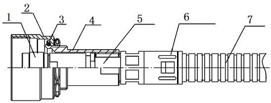
The invention relates to a connector assembly and a plug. The plug is used for a double-sheath cable; it includes a cable connector and a protective sleeve connector; the cable connector includes a first locking cap, and the first locking cap is used to connect with the first external thread on the corresponding socket; the protective sleeve The connector includes a tail shell for fixed connection with the protective sleeve of the double-sheath cable; the second locking cap is used for connecting with the second external thread on the socket; the second locking cap can move backward relative to the tail shell ; A limiting structure is provided between the second locking cap and the tail shell, and the limiting structure is used to prevent the second locking cap from coming out of the tail shell forward. When in use, first move the second locking cap backward relative to the tail shell to expose the first locking cap of the cable connector, then move the second locking cap forward to make the second locking cap reach the connection position, The plug of the present application does not need sheathed cables and protective sheaths of different lengths, which can reduce the difficulty of assembling the plug and double-sheathed cables, and can avoid tearing of the protective sheath.

Description

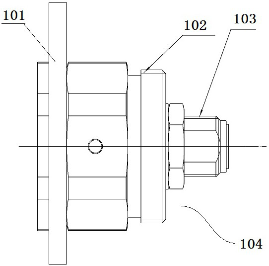
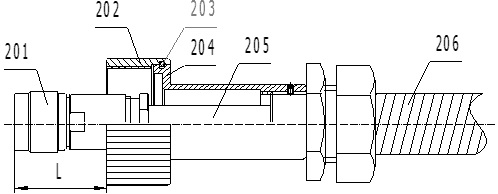
technical field [0001] The invention relates to a connector assembly and a plug. Background technique [0002] When the external environment is relatively harsh, a double-layer connection connector assembly is usually used. The inner layer connection in the double-layer connection realizes signal transmission, and the outer layer connection protects the inner layer connection from the erosion of external sand, stone and rain. [0003] The balise transmission unit (BTM) of the common train control on-board equipment includes the on-board BTM module, the balise antenna and the ground balise, and the three form a point communication system. The feeder connection between the vehicle-mounted BTM module and the transponder antenna uses the connector assembly of the above-mentioned double-layer connection form, specifically: the BTM feeder is a double-sheathed cable, including a sheathed cable 205 and a surrounding set on a sheathed A protective sheath 206 outside the cable 205 , ...

Claims


Application Information

Patent Timeline
Patent Type & Authority Patents(China)
IPC IPC(8): H01R13/502H01R13/623H01R13/52H01R24/00
CPCH01R13/502H01R13/5205H01R13/623H01R24/00
Inventor 王盼盼张志中
Owner CHINA AVIATION OPTICAL-ELECTRICAL TECH CO LTD
Why Eureka
Try Eureka