
Movable laser cleaning equipment for cleaning large workpieces

A laser cleaning and mobile technology, applied in the direction of dust removal, cleaning methods and appliances, and cleaning methods using gas flow, etc., can solve the problems of high cost, complex structure design, and pollution of the laser galvanometer window, etc., to achieve low cost, The effect of simple overall structure

Pending Publication Date: 2020-05-08
山东创瑞增材制造产业技术研究院有限公司
View PDF0 Cites 1 Cited by
  • Summary
  • Abstract
  • Description
  • Claims
  • Application Information

AI Technical Summary

Problems solved by technology

[0003] The object of the present invention is to provide a movable laser cleaning equipment for cleaning large workpieces, so as to solve the problem that the overall structural design of the existing movable laser cleaning equipment proposed in the above-mentioned background technology is relatively complicated, and the cost is high, and at the same time, its The isolation effect on dust is not good, and there will be a certain pollution problem on the laser galvanometer window

Method used


Image

  • Movable laser cleaning equipment for cleaning large workpieces
  • Movable laser cleaning equipment for cleaning large workpieces
  • Movable laser cleaning equipment for cleaning large workpieces

Examples


Embodiment Construction

[0020] The following will clearly and completely describe the technical solutions in the embodiments of the present invention with reference to the accompanying drawings in the embodiments of the present invention. Obviously, the described embodiments are only some, not all, embodiments of the present invention. Based on the embodiments of the present invention, all other embodiments obtained by persons of ordinary skill in the art without making creative efforts belong to the protection scope of the present invention.

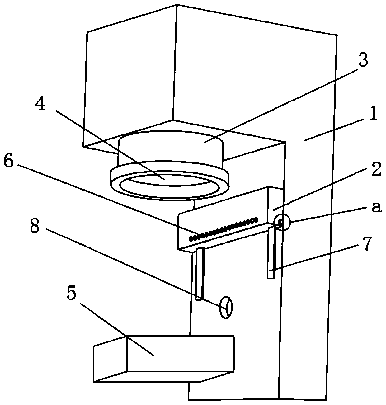
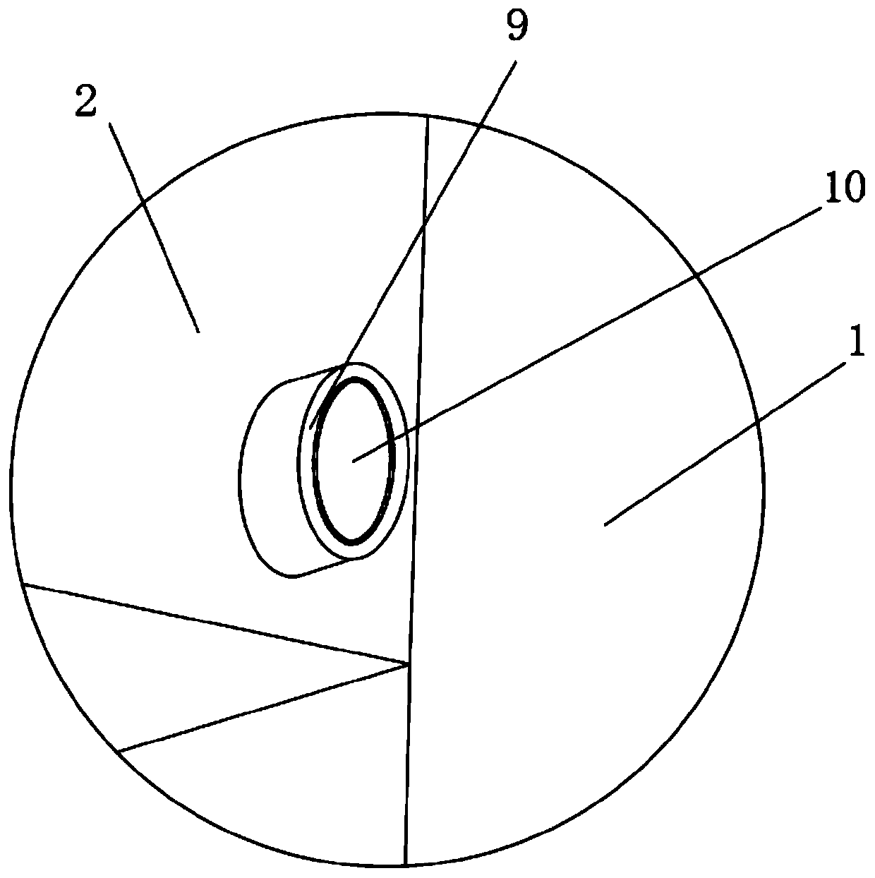
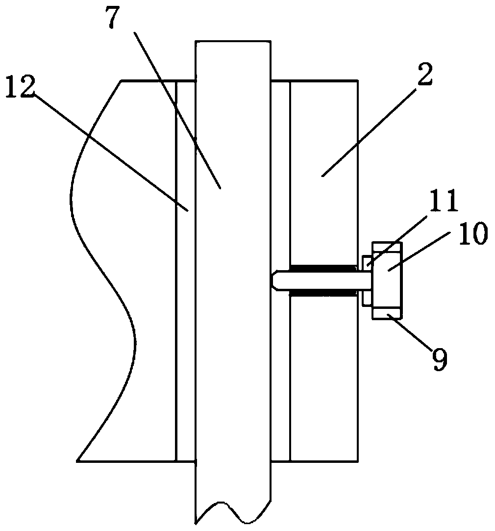
[0021] see Figure 1-Figure 5 , the present invention provides a technical solution: a movable laser cleaning device for cleaning large workpieces, including a vibrating mirror bracket 1, a vibrating mirror 3 is arranged on the inner top of the vibrating mirror bracket 1, and a vibrating mirror window is arranged on the bottom end of the vibrating mirror 3 4. There is a blowing box 2 on the inner side of the vibrating mirror bracket 1, and a dovetail groove 12...


PUM


Abstract

The invention discloses movable laser cleaning equipment for cleaning large workpieces. The movable laser cleaning equipment comprises a galvanometer holder, a galvanometer is arranged at the top endinside the galvanometer holder, a galvanometer window is arranged at the bottom end of the galvanometer, an air blowing box is arranged on one side inside the galvanometer holder, dovetail grooves areformed in both ends of the rear surface of the air blowing box correspondingly, dovetail strips are arranged inside the dovetail grooves, one sides of the dovetail strips are located on one side inside the galvanometer holder, a collection tube is arranged at the bottom end of one side inside the galvanometer holder, the collection tube penetrates through the galvanometer holder, a processing piece is arranged at the bottom end inside the galvanometer holder, the collection tube is located on one side of the top end of the processing piece, the air blowing box is located on one side of the bottom end of the galvanometer, and an air blowing hole is formed in the bottom end of the front surface of the air blowing box. By additionally installing the air blowing box on one side inside the galvanometer holder, the overall structure is relatively simple, the cost is low, in addition, the air blowing box is arranged on the side surface of the galvanometer holder, and thus the load of the galvanometer cannot be increased.

Description

technical field [0001] The invention belongs to the technical field of movable laser cleaning equipment, and in particular relates to a movable laser cleaning equipment for cleaning large workpieces. Background technique [0002] In some laser processing equipment in the prior art, for example, laser marking is pure laser marking without other auxiliary parts, so that there will be some smoke, dust and processing residues attached to the surface of the vibrating mirror during the processing. If these processing residues adhere to the surface of the vibrating mirror and are not cleaned in time, it will affect the processing energy of the laser and even burn the lens. Even if the vibrating mirror is cleaned regularly, the service life of the expensive vibrating mirror will be greatly shortened. In order to prevent the vibrating mirror from being polluted, most of the existing technologies install the blowing protective cover at the window of the vibrating mirror. When the vibr...

Claims


Application Information

Patent Timeline
Patent Type & Authority Applications(China)
IPC IPC(8): B08B5/02B08B15/04B08B13/00B08B7/00
CPCB08B5/02B08B15/04B08B13/00B08B7/0042
Inventor 吕忠利王崇刘春雨
Owner 山东创瑞增材制造产业技术研究院有限公司
Learn More