Punching die mechanism with waste-falling protection sleeve

A technology of die mechanism and protective sleeve, applied in the field of punching die mechanism, can solve the problems of affecting the blanking effect, lack of protective parts, and waste stuck, and achieves the punching effect, the impact force is reduced, and the replacement and maintenance are convenient. Effect

Inactive Publication Date: 2020-05-08
朱福英
View PDF0 Cites 3 Cited by
  • Summary
  • Abstract
  • Description
  • Claims
  • Application Information

AI Technical Summary

Problems solved by technology

[0002] In the existing punching die, the punching tool will punch the middle part of the plate body after the punching tool falls directly, and the waste material dropped from the punching will be in the central through hole of the lower die and fall through the central through hole, while The central through hole of the lower mold generally has no protective parts on the inner side wall, which tends to make the waste material rub against the inner side wall of the central through hole when it falls, and it is easy to wear the inner side wall of the central through hole and become very rough, so it is easy to fall. When scrapping, the scrap will be stuck, which will affect the blanking effect

Method used


Image

  • Punching die mechanism with waste-falling protection sleeve
  • Punching die mechanism with waste-falling protection sleeve
  • Punching die mechanism with waste-falling protection sleeve

Examples


Embodiment

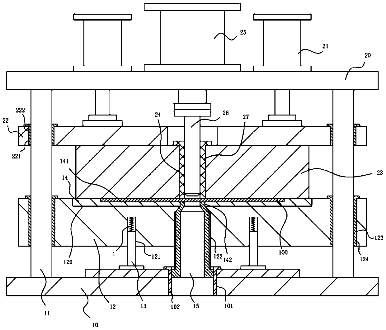
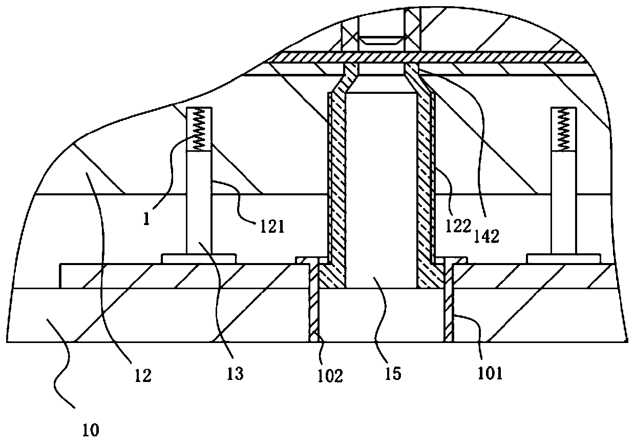
[0019] Example: see Figure 1 to Figure 2 As shown, a punching die mechanism with a blanking protective sleeve includes a lower mold fixed bottom plate 10, a plurality of vertical guide columns 11 are fixed on the top surface edge of the lower mold fixed bottom plate 10, and an upper fixed plate 20 is fixed on the top surfaces of all vertical guide posts 11;

[0020] A lower fixed plate 12 is provided above the fixed bottom plate 10 of the lower mold, and the lower fixed plate 12 is inserted into all vertical guide columns 11, and a plurality of vertical buffer columns 13 are fixed on the top surface of the fixed bottom plate 10 of the lower mold. , the vertical buffer column 13 is inserted into the guide socket 121 formed on the bottom surface of the lower fixing plate 12, the buffer spring 1 is inserted into the guide socket 121, and the bottom end of the buffer spring 1 focuses on the top of the vertical buffer column 13. On the surface, the top of the buffer spring 1 is f...


PUM


Abstract

The invention discloses a punching die mechanism with a waste-falling protection sleeve. The punching die mechanism with the waste-falling protection sleeve comprises a fixed bottom plate of a lower die, wherein a plurality of vertical guide columns are fixed to the side part of the top surface of the fixed bottom plate of the lower die, and an upper fixed plate is fixed to the top surfaces of allthe vertical guide columns; and a lower fixed plate is arranged above the fixed bottom plate of the lower die, all the vertical guide columns are sleeved with the lower fixed plate in an insertion manner, and a plurality of vertical buffer columns are fixed to the side part of the top surface of the fixed bottom plate of the lower die. The punching die mechanism with the waste-falling protectionsleeve is provided with a detachable central screwing sleeve body which is screwed into a central screwing through hole as a protection sleeve for falling of punching wastes, so that the wastes cannotmake contact with the inner sidewall of the central screwing through hole; after the punching die mechanism with the waste-falling protection sleeve is used for a certain time and when the inner sidewall of the central screwing sleeve body is worn, the central screwing sleeve body can be directly detached and replaced, the operation is quite convenient, and the replacement, repair and maintenanceare convenient; and moreover, when an upper die block presses downwards, a buffer effect is realized through buffer springs, and an impact force during the falling of an upper die is reduced, so thatthe punching effect is ensured.

Description

technical field [0001] The invention relates to the technical field of mold equipment, in particular to a punching mold mechanism with a blanking protective cover. Background technique [0002] In the existing punching die, the punching tool will punch the middle part of the plate body after the punching tool falls directly, and the waste material dropped from the punching will be in the central through hole of the lower die and fall through the central through hole, while The central through hole of the lower mold generally has no protective parts on the inner side wall, which tends to make the waste material rub against the inner side wall of the central through hole when it falls, and it is easy to wear the inner side wall of the central through hole and become very rough, so it is easy to fall. When scrapping, the scrap will be stuck, which will affect the blanking effect. Contents of the invention [0003] The purpose of the present invention is to address the defici...

Claims


Application Information

Patent Timeline
Patent Type & Authority Applications(China)
IPC IPC(8): B21D28/34B21D28/26
CPCB21D28/26B21D28/34
Inventor 朱福英
Owner 朱福英
Why Eureka
Try Eureka