Optical centering and edging fixture for plano-convex cylindrical mirror, and optical centering and edging method

A plano-convex cylindrical mirror and edging technology, applied in the field of optics, can solve the problem that the processing efficiency cannot reach the best state, and achieve the effect of reducing the CNC processing technology, improving the production efficiency and quality, and ensuring the center deviation parameter index.

Pending Publication Date: 2020-05-08
FOCTEK PHOTONICS LNC
View PDF0 Cites 2 Cited by
  • Summary
  • Abstract
  • Description
  • Claims
  • Application Information

AI Technical Summary

Problems solved by technology

This method is easy to meet the requirements of surface shape and smoothness, but due to the special processing technology

Method used


Image

  • Optical centering and edging fixture for plano-convex cylindrical mirror, and optical centering and edging method
  • Optical centering and edging fixture for plano-convex cylindrical mirror, and optical centering and edging method
  • Optical centering and edging fixture for plano-convex cylindrical mirror, and optical centering and edging method

Examples


Embodiment 1

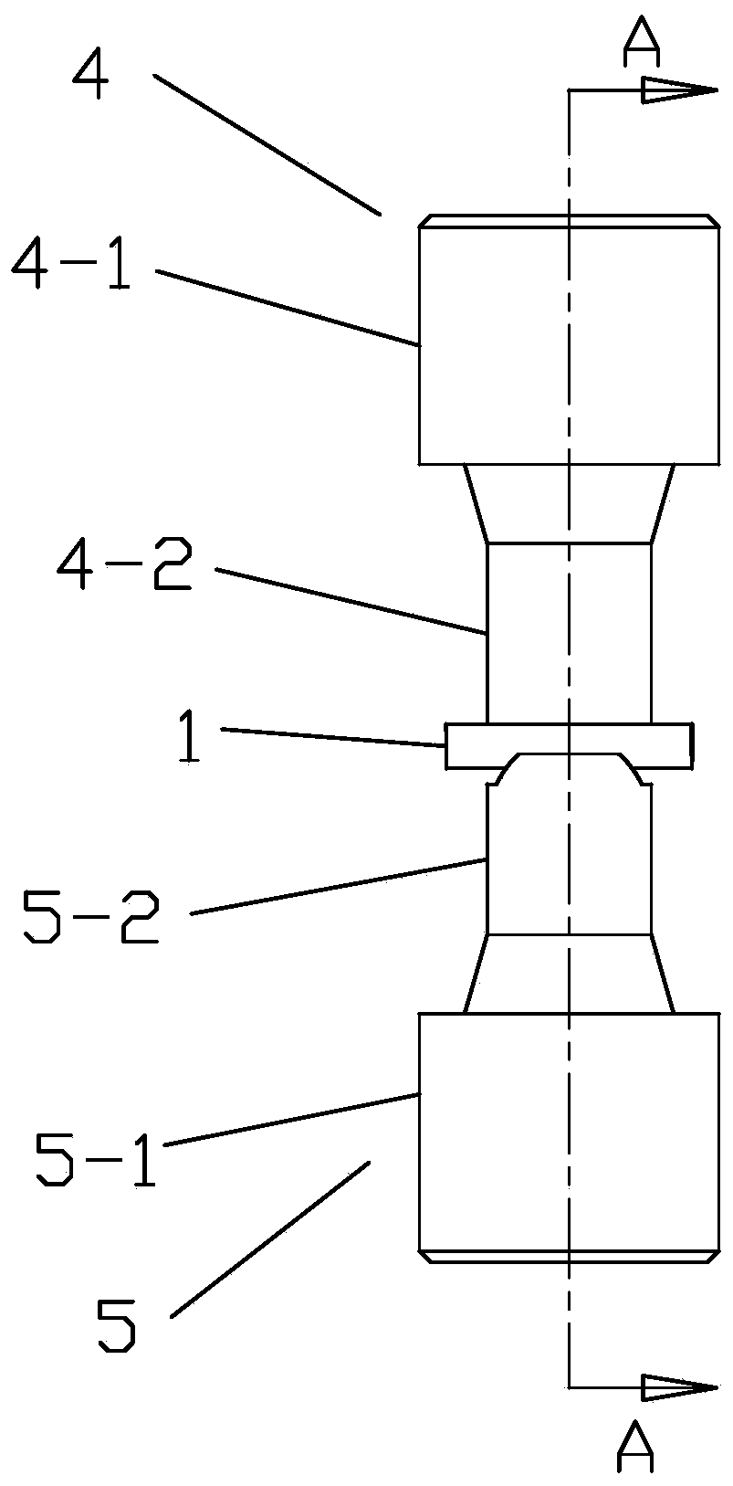
[0046] Such as Figure 1-7 As shown, an optical centering and edging fixture of a plano-convex cylindrical mirror, the optical centering and edging fixture of a plano-convex cylindrical mirror includes a first clamping assembly 4 and a second clamping assembly that are opposite and coaxially arranged The holding assembly 5; the first holding assembly 4 includes the first seat cover 4-1 fixed on the optical centering edger and the first clamping sleeve connected to the axial end of the first seat cover 4-1 The barrel 4-2, the first seat cover 4-1 is provided with a first fixing hole 4-1-1 extending in the axial direction for installation and connection with the optical centering and edging instrument. A clamping sleeve 4-2 is provided with a first light passage 4-2-1 extending in the axial direction, the first fixing hole 4-1-1 and the first light passage 4- 2-1 Interpenetrating and coaxial arrangement;

[0047] The second clamping assembly 5 includes a second seat cover 5-1 fi...


PUM

PropertyMeasurementUnit
Apertureaaaaaaaaaa
Thicknessaaaaaaaaaa

Abstract

The invention relates to an optical centering and edging fixture for a plano-convex cylindrical mirror. The optical centering and edging fixture for the plano-convex cylindrical mirror comprises a first clamping component and a second clamping component, wherein the first clamping component and the second clamping component are opposite and are coaxially arranged; the second clamping component comprises a second clamping sleeve; in the second clamping sleeve, a straight slot is arranged on a connection position of the sleeve wall and the top end surface of the second clamping sleeve; the slotopening of the straight slot faces one side of the top end surface, and the width of the slot opening is greater than the aperture of a second light transmission pore passage; two slot side walls of the straight slot are formed by one pair of inclined planes which are symmetrically arranged by taking an axial line as a symmetric center; intersecting lines of the two inclined planes and the top endsurface of the second clamping sleeve are mutually in parallel; and in addition, an inclination direction of the two inclination planes enables the width of the slot opening to be greater than the width of a slot bottom. By use of the V-shaped fixture of the invention, the plano-convex cylindrical mirror can be effectively tightly clamped and is unlikely to automatically move during fixation, then, a central bus display position is regulated through optical centering, and therefore, a decentration parameter index is effectively guaranteed.

Description

technical field [0001] The invention relates to the field of optics, in particular to an optical centering and edging jig for a plano-convex cylindrical mirror and a method for optical centering and edging. Background technique [0002] The disc plano-convex cylindrical mirror is suitable for many occasions, and relative to the various parameters of the disc plano-convex cylindrical mirror are gradually increasing. The increase of the parameter index not only means the increase of processing difficulty, but also increases the processing cost. [0003] At present, there are two main processing methods for plano-convex cylindrical mirrors: [0004] 1. The blank is in the form of a disc, and the cylindrical surface is processed through the subsequent process. On the one hand, this method of processing is not easy to control the product's surface shape, smoothness, and center deviation. On the other hand, it takes a long time for processing assistance, and the overall efficien...

Claims


Application Information

Patent Timeline
IPC IPC(8): B24B9/14B24B41/06
CPCB24B9/14B24B9/146
Inventor 蔡捷丞陈昕
Owner FOCTEK PHOTONICS LNC
Why Eureka
Try Eureka