High-speed paper bag bottom gluing device

A gluing device and paper bag technology, applied in packaging, papermaking, bag making operations, etc., can solve problems affecting the speed of paper bags, easily damaged machines, blockages, etc., and achieve the effects of ensuring gluing quality, solving efficiency, and facilitating folding and forming

Pending Publication Date: 2020-05-08
上豪包装机械(镇江)有限公司
View PDF0 Cites 8 Cited by
  • Summary
  • Abstract
  • Description
  • Claims
  • Application Information

AI Technical Summary

Problems solved by technology

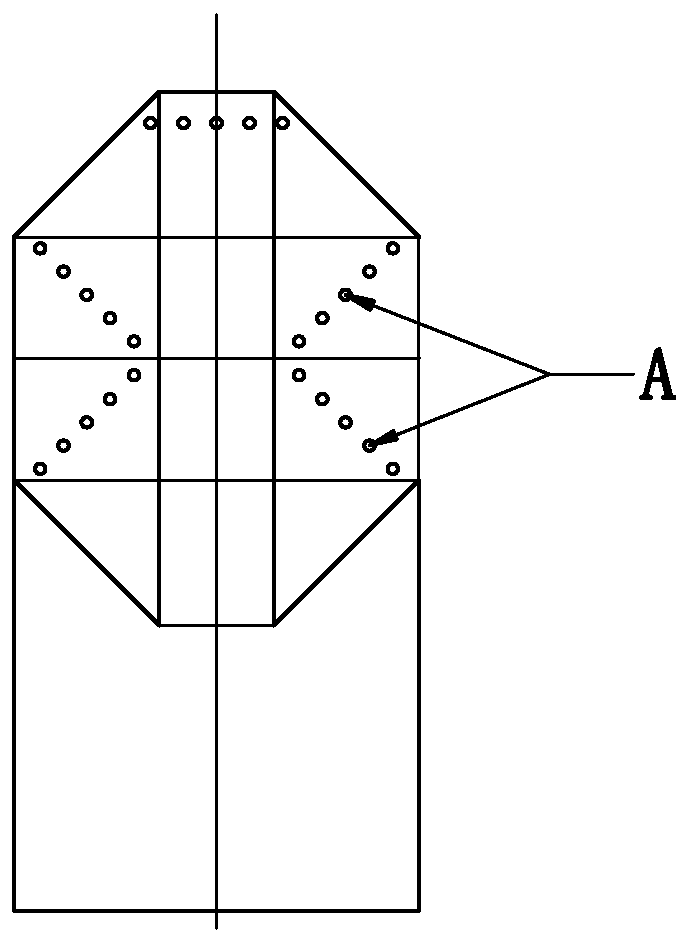
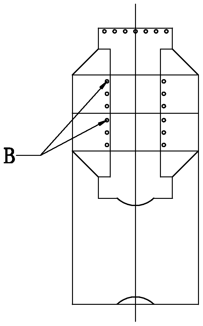
[0002] Nowadays, paper bags have realized automatic production, among which folding the edges into tubes, creasing the bag bottom, applying bag bottom glue, bag bottom folding, and collecting have corresponding devices; for the process of bag bottom glue coating, traditional bag coating The bottom glue adopts the matching structure of the glue sizing board and the glue transfer roller to carry out transmission and glue application. The glue application position of the paper bag is as follows: figure 1 The locus of point A and figure 2 The position indicated by the trajectory of point B of the paper bag with a square bottom, the existing transmission glue, when the running speed is slow, the glue can not be thrown out, but the glue will be thrown out when the speed reaches more than 250 pieces per minute, and the glue will splash on the paper bag On the machine, the paper bag is blocked and easily damaged, so it cannot be produced continuously. After a long time, it will inevitably affect the normal operation of the machine, and the quality of glue coating is not easy to guarantee. Therefore, the general equipment can only be opened to about 200 per minute. At this time, it will Seriously affect the speed of paper bags and greatly reduce the production efficiency of paper bag machines

Method used


Image

  • High-speed paper bag bottom gluing device
  • High-speed paper bag bottom gluing device
  • High-speed paper bag bottom gluing device

Examples


Embodiment Construction

[0023] The high-speed paper bag bottom gluing device of the present invention will be described in further detail below in conjunction with the accompanying drawings and specific embodiments.

[0024] As shown in the figure, the high-speed paper bag bottom gluing device of the present invention includes a gluing shaft 2 with a glue inlet pipeline 1, a gluing roller 3 sleeved on the gluing shaft, and a plurality of gluing rollers arranged on the periphery of the gluing roller. The glue spray head 4 can be designed according to the specifications of the paper bag with several differently arranged glue spray heads 4. The glue spray roller 3 is sealed and installed on the sizing shaft and there is a gap between the glue spray roller and the sizing shaft so that the glue can enter from the glue. The annular cavity 5 into which the pipeline enters is formed by Figure 4 It can be seen that the glue inlet pipeline 1 is opened from one end of the gluing shaft and extends to the middle...


PUM


Abstract

The invention discloses a high-speed paper bag bottom gluing device. The high-speed paper bag bottom gluing device comprises a glue applying shaft, a glue spraying roller arranged on the glue applyingshaft in a sleeving mode and a plurality of glue spraying heads, wherein the glue spraying roller is installed on the glue applying shaft in a sealed mode, so that an annular cavity allowing glue tobe fed from an inlet pipeline is formed between the glue spraying roller and the glue applying shaft, each glue spraying head comprises a valve seat installed on the glue spraying roller, a valve element arranged in the corresponding valve seat, a compressed spring abutting against the bottom of the corresponding valve element and a sealing ring arranged at a glue outlet of the corresponding valveseat, the upper ends of the valve elements can stretch out of the glue outlets formed in the tops of the valve seats and can seal the glue outlets by using the sealing rings under the action of the compressed springs, and the glue spraying heads can enable the valve elements to overcome spring force to enable the glue outlets to discharge the glue in the glue applying process. The high-speed paper bag bottom gluing device has the advantages that high-speed running of more than 500 paper bags per minute can be achieved, the glue is not thrown, the bottoms of the paper bags are stably and automatically coated with the glue, the paper bags can be conveniently folded and formed, so that the gluing quality is guaranteed, continuous automatic production can be achieved, and then the problem ofthe efficiency of a paper bag machine is solved.

Description

technical field [0001] The invention relates to an accessory device of a paper bag machine, in particular to a high-speed paper bag bottom gluing device. Background technique [0002] Nowadays, paper bags have realized automatic production, among which folding the edges into tubes, creasing the bag bottom, applying bag bottom glue, bag bottom folding, and collecting have corresponding devices; for the process of bag bottom glue coating, traditional bag coating The bottom glue adopts the matching structure of the glue sizing board and the glue transfer roller to carry out transmission and glue application. The glue application position of the paper bag is as follows: figure 1 The locus of point A and figure 2 The position indicated by the trajectory of point B of the paper bag with a square bottom, the existing transmission glue, when the running speed is slow, the glue can not be thrown out, but the glue will be thrown out when the speed reaches more than 250 pieces per mi...

Claims


Application Information

Patent Timeline
Patent Type & Authority Applications(China)
IPC IPC(8): B31B70/62B31B70/00B31B160/20
CPCB31B70/006B31B70/62B31B2160/20
Inventor 朱东
Owner 上豪包装机械(镇江)有限公司
Why Eureka
Try Eureka