Printer core, fixing mechanism of rubber roller shaft sleeve of printer core and thermal printer

A technology of printing core and fixing mechanism, applied in printing, transfer materials, power transmission devices, etc., can solve the problems of elastic fatigue fracture, printing failure and loss of printing core

Pending Publication Date: 2020-05-08
XIAMEN PINNACLE ELECTRICAL
View PDF0 Cites 0 Cited by
  • Summary
  • Abstract
  • Description
  • Claims
  • Application Information

AI Technical Summary

Problems solved by technology

Its disadvantage is that the spring wire retaining spring 3 is an independent part and is mounted on the main support 1 of the printer core. During its use, it often occurs that the metal spring wire retaining spring 3 is disengaged from the main support 1 when it is dropped. The phenomenon of fatigue fracture and its not being stuck in place during the installation process, which leads to the failure of the printing core to print

Method used


Image

  • Printer core, fixing mechanism of rubber roller shaft sleeve of printer core and thermal printer
  • Printer core, fixing mechanism of rubber roller shaft sleeve of printer core and thermal printer
  • Printer core, fixing mechanism of rubber roller shaft sleeve of printer core and thermal printer

Examples


Embodiment Construction

[0022] To further illustrate the various embodiments, the present invention is provided with accompanying drawings. These drawings are a part of the disclosure of the present invention, which are mainly used to illustrate the embodiments, and can be combined with related descriptions in the specification to explain the operating principles of the embodiments. With reference to these contents, those skilled in the art should understand other possible implementations and advantages of the present invention. Components in the figures are not drawn to scale, and similar component symbols are generally used to denote similar components.

[0023] The present invention will be further described in conjunction with the accompanying drawings and specific embodiments.

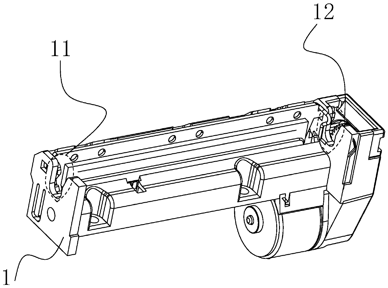
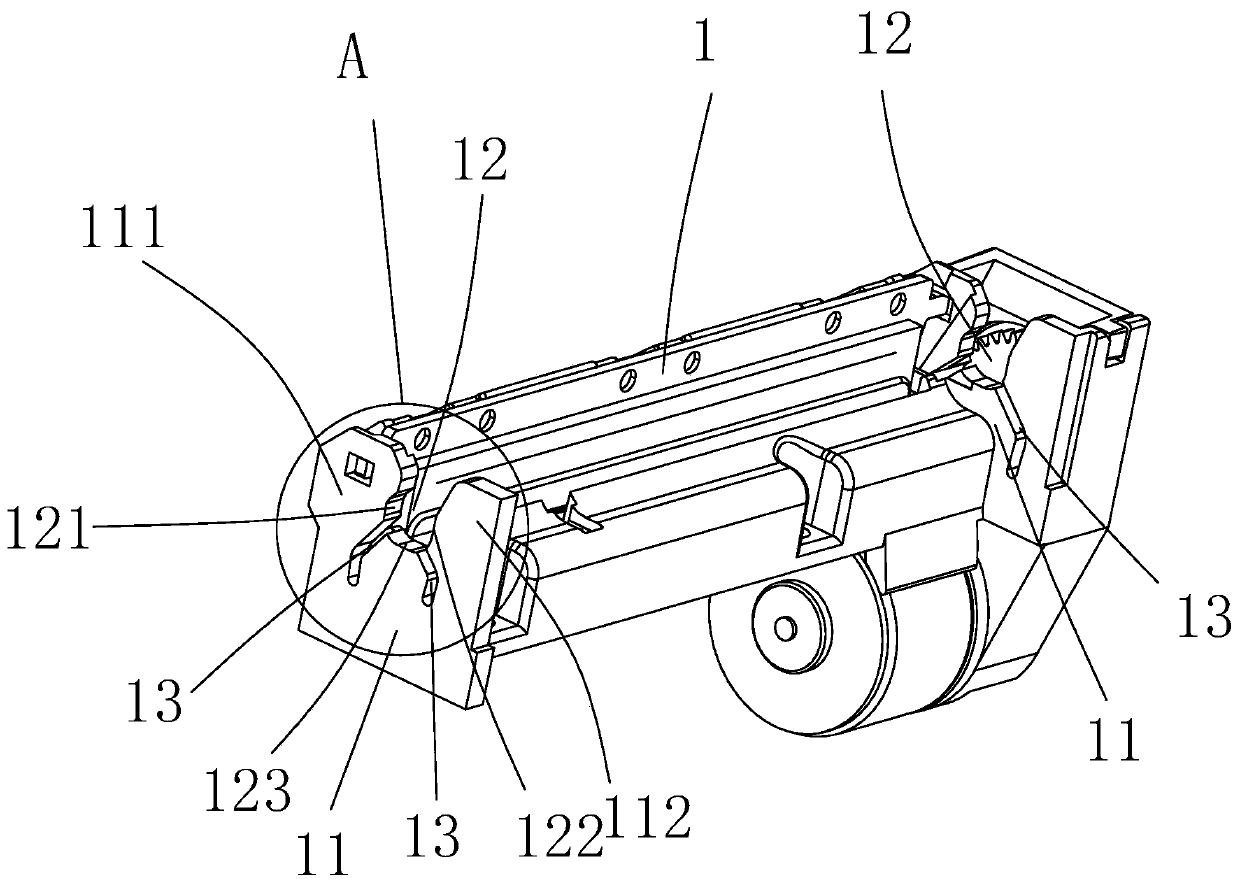
[0024] Such as Figure 3-5 As shown, a fixing mechanism for the rubber roller bushing of a printing core includes positioning grooves 12 arranged on the main support 1 of the printing core. Specifically, the number of ...


PUM


Abstract

The invention discloses a printer core and a fixing mechanism of a rubber roller shaft sleeve of the printer core. The fixing mechanism of the rubber roller shaft sleeve of the printer core comprisesa left shaft sleeve seat and a right shaft sleeve seat which are located on the left side wall and the right side wall of a printer respectively, the two shaft sleeve seats are of the same structure,each shaft sleeve seat is provided with a left bottom groove and a right bottom groove, and the semicircular-opening shaft sleeve seats with upper openings are changed into three-part shaft sleeve seats with left parts, right parts and bottom parts through grooving. The left parts and the right parts are changed into elastic shaft sleeve clamping walls capable of being opened leftwards and rightwards, so that the shaft sleeve can elastically open narrow openings when passing through the narrow openings above the shaft sleeve seats, the shaft sleeve enters a working position of the shaft sleeveseats through the narrow openings under a preset pressure value, the narrow openings rebound to the original positions, and the shaft sleeve is clamped by the rebounded left and right walls to work correctly. According to the printer core and the fixing mechanism, the rubber roller shaft sleeve can be clamped by the elastic force of the three-part shaft sleeve seats without a metal elastic wire clamp spring, and the three-part shaft sleeve seats and a main bracket of the printer core are of an integrated structure, so that the problem that the traditional metal elastic wire clamp spring fallsoff during installation and use is avoided, and the cost is saved.

Description

technical field [0001] The invention belongs to the field of printer structure, and in particular relates to a fixing mechanism of a rubber roller sleeve of a printing core, a printing core and a thermal printer. Background technique [0002] The printing core of a thermal printer generally includes a main frame with a printing core and a rubber roller rotatably mounted on the main frame. The printing core is installed in the thermal printer and the power source in the printer drives the rubber roller to rotate to achieve printing. [0003] Such as figure 1 and 2 As shown, in the field of thermal printing cores, the traditional way to fix the rubber roller assembly 2 of the printing core is to use the metal elastic wire retaining spring 3, which is installed in the card slot of the main bracket 1 of the printing core to press the rubber roller assembly 2 The left bearing 21 and the right bearing 22, make the left bearing 21 and the right bearing 22 be positioned in the "U"...

Claims


Application Information

Patent Timeline
Patent Type & Authority Applications(China)
IPC IPC(8): B41J2/32B41J25/00
CPCB41J2/32B41J25/00
Inventor 钮李明
Owner XIAMEN PINNACLE ELECTRICAL
Why Eureka
Try Eureka