A static pressure gas thrust bearing
A thrust bearing and gas technology, applied in the direction of air cushion bearings, bearings, shafts and bearings, etc., can solve the problems of air hammer vibration, bearing failure, restriction of small hole throttling static pressure gas thrust bearing capacity improvement, etc., to achieve gas supply Increased pressure, improved bearing capacity, good air hammer stability
- Summary
- Abstract
- Description
- Claims
- Application Information
AI Technical Summary
Problems solved by technology
Method used
Image
Examples
Embodiment 1
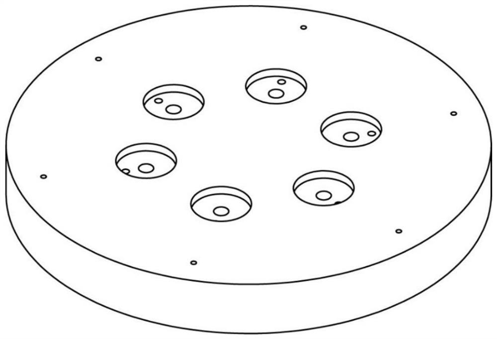
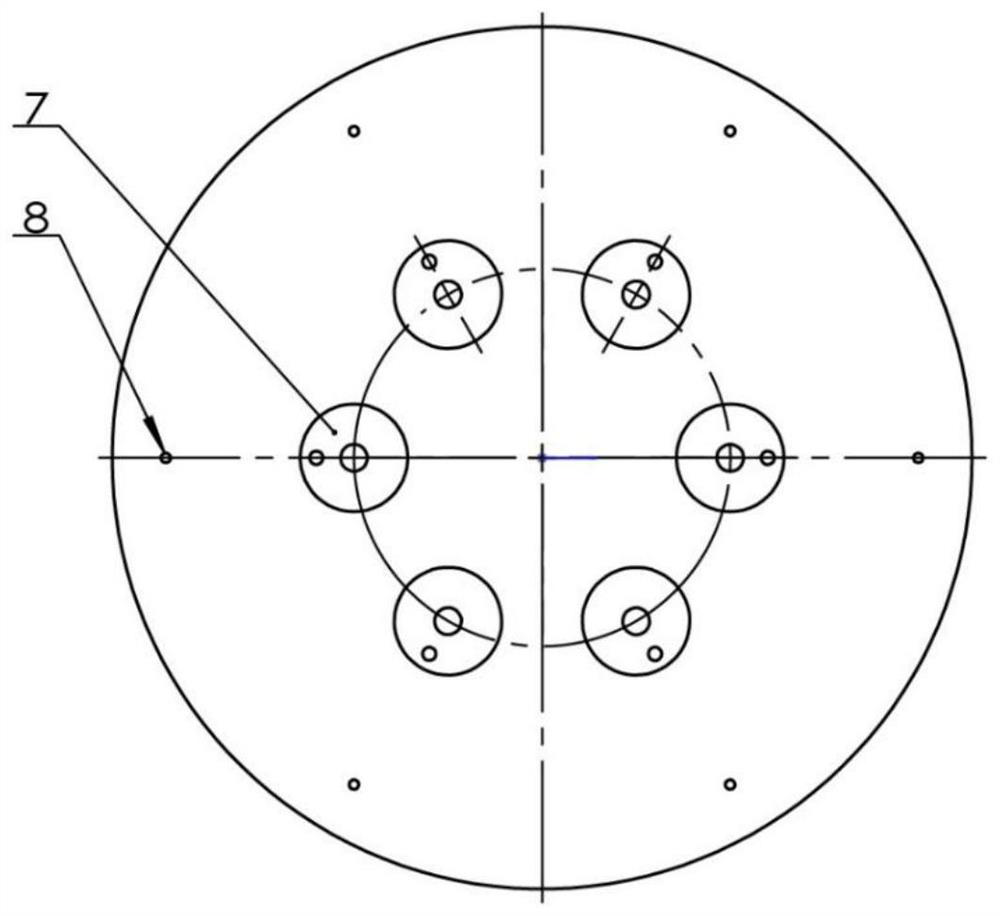
[0031] figure 1 It is a schematic diagram of the overall structure of the bearing of the present invention; Figure 4 It is a schematic diagram of the local structure between the small hole restrictor 3 and the unloading channel 4, and the position where the unloading channel 4 communicates with the pressure equalizing chamber 7 is far away from the center of the bearing. The bottom of the equalizing chamber 7 is connected with the unloading channel 4, and the unloading channel 4 is connected with the guide channel 5, and the guide channel 5 enters the annular restrictor 8 through the return channel 6.
[0032] The annular restrictor (8) is designed as one circle, and the outlet diameters of each annular restrictor on the same circle are designed to be the same. The number of annular restrictors (8) is 6, and the two adjacent annular restrictors The angle formed by the line connecting the center of the restrictor and the center of the bearing is 60°.
Embodiment 2
[0034] The basic structure of this embodiment is the same as that of Embodiment 1. The difference is that the number of annular restrictors in this embodiment is set to four, and the connection line between the center of two adjacent annular restrictors and the center of the bearing The angle formed is 90°, such as Figure 8 shown.
Embodiment 3
[0036] The basic structure of this embodiment is the same as that of Embodiment 1, the difference is that in this embodiment, the design of the annular restrictor is 2 turns, the number of the first ring of annular restrictors is 4, and the second ring of annular restrictor The number of devices is 4; the angle formed by the center of two adjacent annular restrictors in each circle and the center of the bearing is 90°; for all annular restrictors, the angle between the two adjacent annular restrictors The angle formed by the center of the surface restrictor and the center of the bearing is 45°, such as Figure 9 shown.
PUM
 Abstract
Description
Claims
Application Information
 - R&D
- Intellectual Property
- Life Sciences
- Materials
- Tech Scout
- Unparalleled Data Quality
- Higher Quality Content
- 60% Fewer Hallucinations
Browse by: Latest US Patents, China's latest patents, Technical Efficacy Thesaurus, Application Domain, Technology Topic, Popular Technical Reports.
© 2025 PatSnap. All rights reserved.Legal|Privacy policy|Modern Slavery Act Transparency Statement|Sitemap|About US| Contact US: help@patsnap.com


