Eureka AIR delivers breakthrough ideas for toughest innovation challenges, trusted by R&D personnel around the world.

Gas turbine moving blade pressurizing and cooling structure utilizing rotation effect

A technology of cooling structure and gas turbine, which is applied to engine components, climate sustainability, machines/engines, etc. It can solve problems such as large pressure gradients, achieve the effect of enhancing the supercharging effect and reducing the pressure demand

Active Publication Date: 2022-02-08
XI AN JIAOTONG UNIV
View PDF5 Cites 0 Cited by
  • Summary
  • Abstract
  • Description
  • Claims
  • Application Information

AI Technical Summary

Problems solved by technology

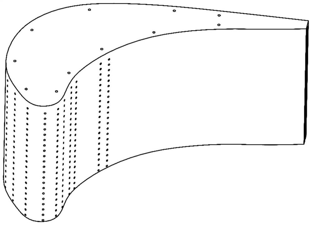
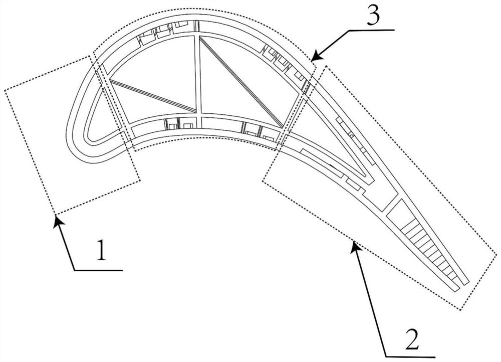
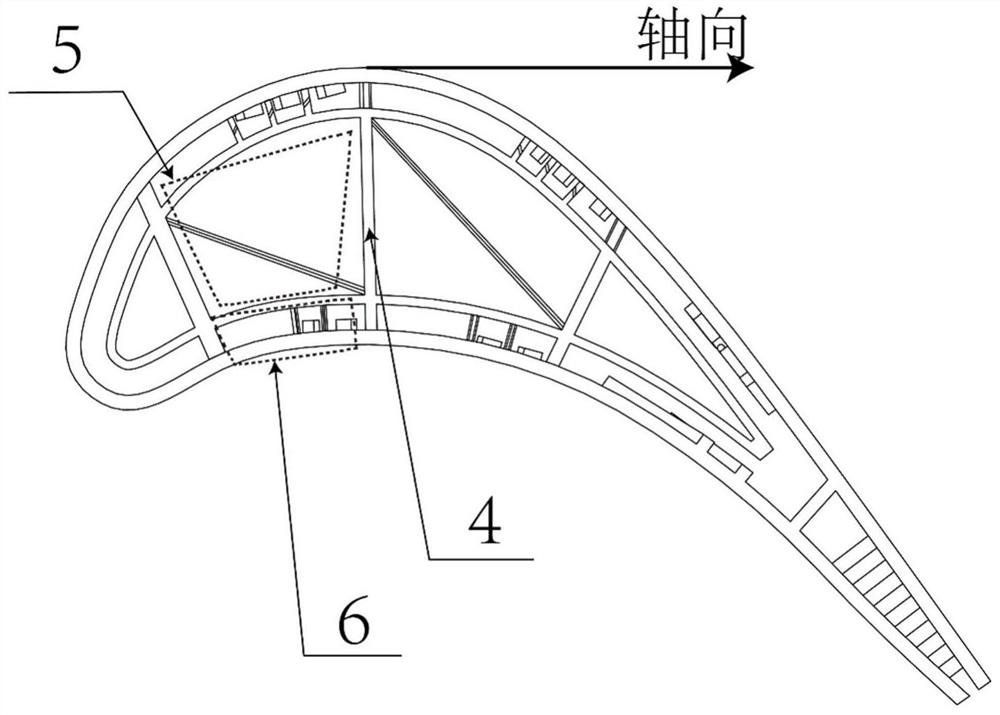
[0004] The purpose of the present invention is to provide a gas turbine moving blade pressurized cooling structure utilizing the rotation effect, and improve the strength of the blade through the Z-shaped rotary pressurized cavity with a triangular structure; The separation makes the rotating Coriolis force always point to the impact-convection series cooling laminates when the cooling air flow in the air supply chamber moves radially, which not only improves the air supply pressure of the impact-convection series cooling laminates, but also effectively solves the high speed condition Excessive pressure gradient between downforce side and suction side cooling airflow

Method used


Image

  • Gas turbine moving blade pressurizing and cooling structure utilizing rotation effect
  • Gas turbine moving blade pressurizing and cooling structure utilizing rotation effect
  • Gas turbine moving blade pressurizing and cooling structure utilizing rotation effect

Examples


Embodiment Construction

[0036] Exemplary embodiments of the present disclosure will be described in more detail below with reference to the accompanying drawings. Although exemplary embodiments of the present disclosure are shown in the drawings, it should be understood that the present disclosure may be embodied in various forms and should not be limited by the embodiments set forth herein. Rather, these embodiments are provided for more thorough understanding of the present disclosure and to fully convey the scope of the present disclosure to those skilled in the art. It should be noted that, in the case of no conflict, the embodiments of the present invention and the features in the embodiments can be combined with each other. The present invention will be described in detail below with reference to the accompanying drawings and examples.

[0037] In order to make the purpose, technical effect and technical solution of the present invention more clear, the following will be clearly and completely...


PUM


Abstract

The invention discloses a gas turbine moving blade pressurizing and cooling structure utilizing the rotation effect. The structure is specifically composed of a flow direction middle partition plate, a Z-shaped rotary pressurizing cavity arranged in a multi-stage mode and impact-convection series cooling laminates which are all located in a gas turbine moving blade, the Z-shaped rotary pressurizing cavity divides a pressure surface and a suction surface gas supply cavity and organize the radial flow direction in the gas supply cavity, the rotary Coriolis force is used for improving the air supply pressure of the impact-convection series cooling laminates and reducing the air supply pressure gradient between the suction surface and the pressure surface; and the Reynolds number of the impact-convection series-connection cooling laminates is increased by collecting impact cooling airflow, transverse vortexes formed by rotating Coriolis force in a radial convection heat exchange cavity are enhanced by adopting radial flow guide partition plates with flow guide jet seams, and the heat transfer coefficient is effectively increased. The requirements for cooling air exhaust pressure and air exhaust amount can be lowered through the rotation effect, and the cooling performance is effectively enhanced.

Description

technical field [0001] The invention belongs to the technical field of gas turbine turbine cooling, and in particular relates to a gas turbine moving vane booster cooling structure utilizing the rotation effect. Background technique [0002] Due to its compact size, light weight, high power, fast start-up and other advantages, gas turbines are widely used in many industrial fields such as aerospace, ship power, etc., and play an important role in the national economic life. As the core component, the turbine blade directly works in the In extremely high-temperature gas, the inlet temperature even exceeds the melting point of the superalloy. In order to ensure the safe operation and working life of the gas turbine and improve the overall performance, it is necessary to effectively cool the gas turbine blades. [0003] The traditional blade cooling structure is usually designed and tested based on the aerodynamic process under static conditions, but the rotation effect of the ...

Claims


Application Information

Patent Timeline
Patent Type & Authority Applications(China)
IPC IPC(8): F01D5/18F01D25/00
CPCF01D5/186F01D25/00Y02T50/60
Inventor 张荻杨立克杜秋晚谢永慧
Owner XI AN JIAOTONG UNIV
Why Eureka
Eureka Blog
Learn More