
Rapid butt joint optimized wiring plant lamp device

A plant lamp and wiring technology, which is applied to lighting devices, botany equipment and methods, components of lighting devices, etc., can solve the problem that the distance between lamps cannot be adjusted conveniently, the installation and disassembly of connectors is inconvenient, and the plant planting is affected Take care of other issues, to achieve the effect of reducing inventory costs, wide range of use, and reducing multiple models

Pending Publication Date: 2020-05-08
FUJIAN SANAN SINO SCI PHOTOBIOTECH CO LTD
View PDF0 Cites 0 Cited by
  • Summary
  • Abstract
  • Description
  • Claims
  • Application Information

AI Technical Summary

Problems solved by technology

The plant lamps used at this stage need to drag a long power cord to connect with the multi-wire. The way of connecting the connectors is to tighten the nut or rotate and insert, and the distance between the lamp and the lamp is affected by the length of the power cord. The impact cannot be easily adjusted
This leads to the messy interlacing between the power wires and the plants, and the installation and removal of the connectors is extremely inconvenient. It is beautiful and has certain potential safety hazards, and it needs to spend more on wire materials, which cannot achieve a green economy
Common coiling devices, such as power line reels, are large in size and high in cost; signal lines or charging lines for small electrical appliances are complex in structure and cannot be used for power lines that can carry large currents

Method used


Image

  • Rapid butt joint optimized wiring plant lamp device
  • Rapid butt joint optimized wiring plant lamp device
  • Rapid butt joint optimized wiring plant lamp device

Examples


Embodiment Construction

[0032] In order to explain in detail the technical content, structural features, achieved goals and effects of the technical solution, the following will be described in detail in conjunction with specific embodiments and accompanying drawings.

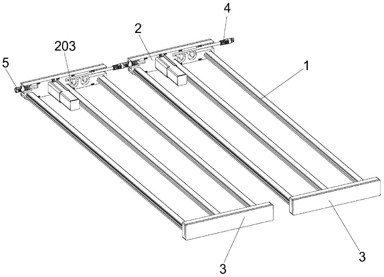
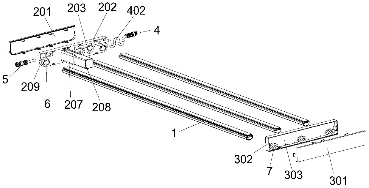
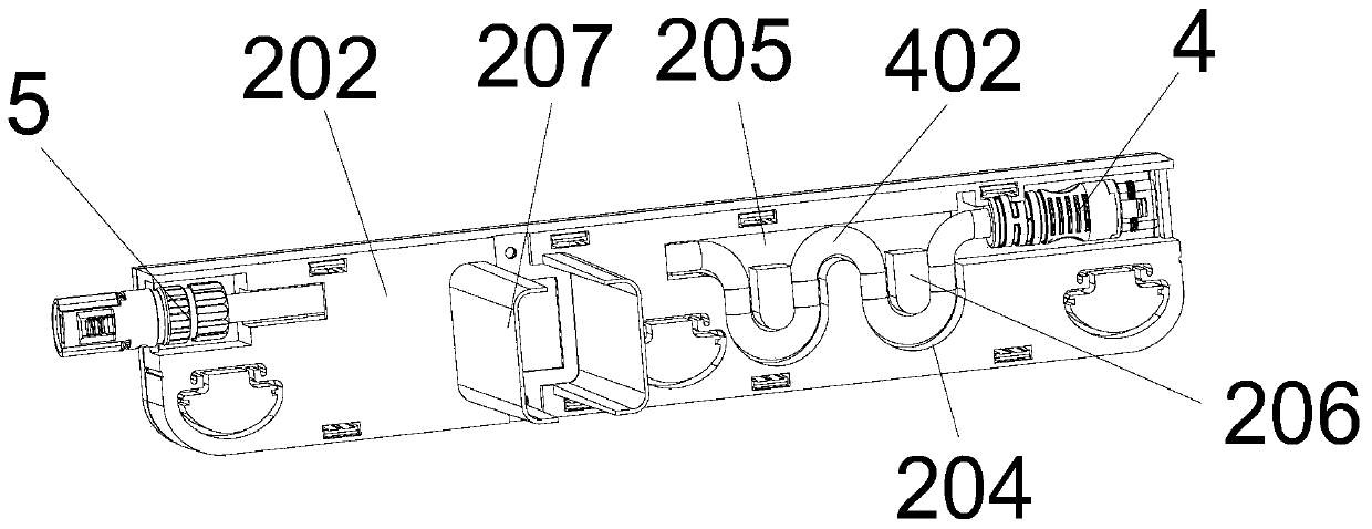
[0033] see Figure 1-Figure 8 In this embodiment, a fast docking optimized wiring plant lamp device includes six lamp bodies 1 and two connecting parts 2. In other embodiments, the lamp body 1 can be nine, the connecting parts 2 can be three, and the lamp body 1 three and three increments, the connecting parts 2 are incremented one by one, not shown in the drawings, the six lamp bodies 1 are divided into two groups on average, and the two groups of lamp bodies 1 are respectively arranged on the two connecting parts 2, and the two Both symmetrical ends of the connecting part 2 are respectively connected with a male end connector 4 and a female end connector 5 matching the male end connector 4, and the two connecting parts 2 are connect...


PUM


Abstract

The invention relates to the technical field of LED lamps, in particular to a rapid butt joint optimized wiring plant lamp device. The lamp device comprises a plurality of lamp bodies and a pluralityof connecting parts, and the plurality of lamp bodies are arranged on the plurality of connecting parts. The two ends of each connecting part are respectively connected with a male end connector and afemale end connector, and the plurality of connecting parts are sequentially connected through the male end connectors and the female end connectors. The male end connectors are connected with the connecting parts through connecting wires, the connecting parts are provided with take-up grooves, and the connecting wires are wound in the take-up grooves. The lamp can be quickly combined, disassembled and maintained through the simple plug-in male and female connectors, so that the quick connection is quicker, the use of lamp wires is saved, and the labor cost and the production cost are reduced.

Description

technical field [0001] The invention relates to the technical field of LED lamps, in particular to a fast-docking optimized wiring plant lamp device. Background technique [0002] At present, as an energy-saving cold light source, LED has the characteristics of high luminous efficiency, small size and long life, and its application in lamps has become more and more popular. Common household lighting, commercial lighting, special lighting, and agricultural lighting that have emerged in recent years are increasingly dependent on LEDs. Plant lighting is one of the fastest-growing industries in the field of agricultural lighting in recent years. Its use of increasingly mature packaging, spectrum and devices has led various lighting companies to enter the plant lighting industry, and its development prospects are unprecedented. [0003] The following problems exist in the prior art. LED lamps are commonly used in the fields of supplementary light in greenhouses, supplementary li...

Claims


Application Information

Patent Timeline
Patent Type & Authority Applications(China)
IPC IPC(8): F21S9/00F21V17/16F21V19/00F21V23/06A01G9/20F21Y115/10
CPCF21S9/00F21V17/164F21V19/0025F21V23/06A01G9/20F21Y2115/10
Inventor 赖泽雄曾亮伍婵娟李娜娜
Owner FUJIAN SANAN SINO SCI PHOTOBIOTECH CO LTD
Learn More