
Wireless movable air conditioning unit

A mobile air conditioner and mobile air conditioner technology, applied in air conditioning systems, heating methods, space heating and ventilation, etc., can solve the problems of low energy efficiency of equipment, large noise pollution, mobile equipment, etc., to avoid waste of cooling capacity, recharge energy The effect of high energy efficiency and increased flexibility

Active Publication Date: 2020-05-08
TONGJI UNIV
View PDF17 Cites 1 Cited by
  • Summary
  • Abstract
  • Description
  • Claims
  • Application Information

AI Technical Summary

Problems solved by technology

[0003] However, in practical applications, the structural design of the traditional mobile air conditioner integrating the refrigeration system and the air supply device has the following disadvantages: 1. It is necessary to connect the power line and the external exhaust duct, and place the outlet of the external exhaust duct on the Outdoors, the range of movement is limited, and the equipment cannot be moved freely and flexibly; 2. The compressor is placed inside the body, and the indoor noise pollution is large; 3. Since the mobile air conditioner needs to be forced to exhaust outdoors through the exhaust duct, Indoor ventilation frequency is high, air conditioning load is large, and the cooling / heating effect is not as good as that of split air conditioners; 4. The equipment is compact in structure and the heat exchanger space is limited, resulting in low energy efficiency of the equipment
However, this solution cannot realize the separation of the dehumidification module and the energy storage module in the terminal of the mobile air conditioner, and the charging station cannot realize the function of simultaneously charging the energy storage module and regenerating the dehumidification module

Method used


Image

  • Wireless movable air conditioning unit
  • Wireless movable air conditioning unit
  • Wireless movable air conditioning unit

Examples


Embodiment

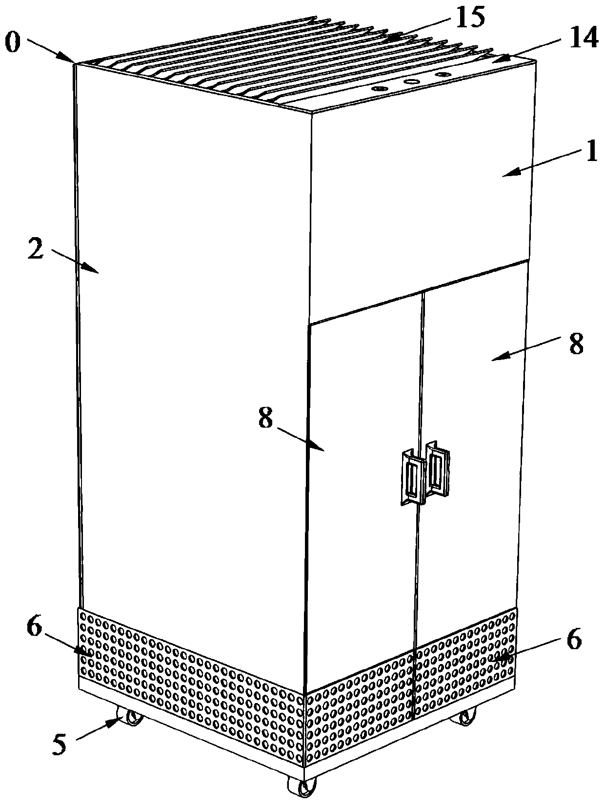
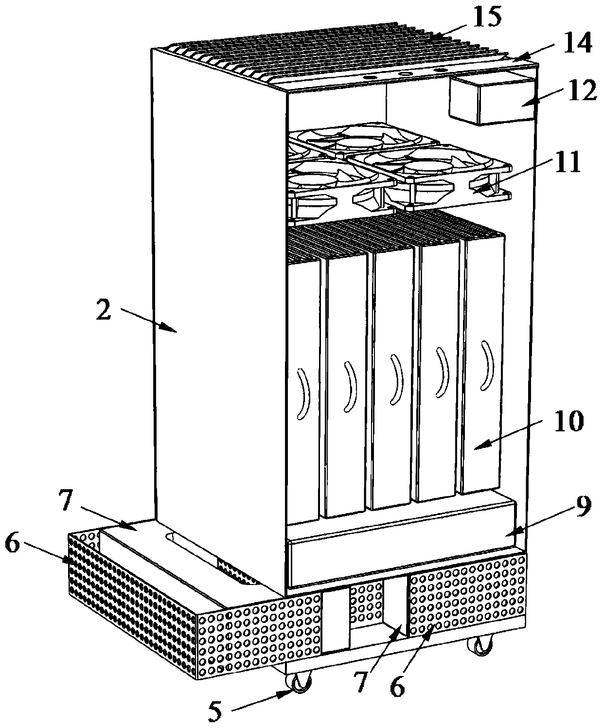
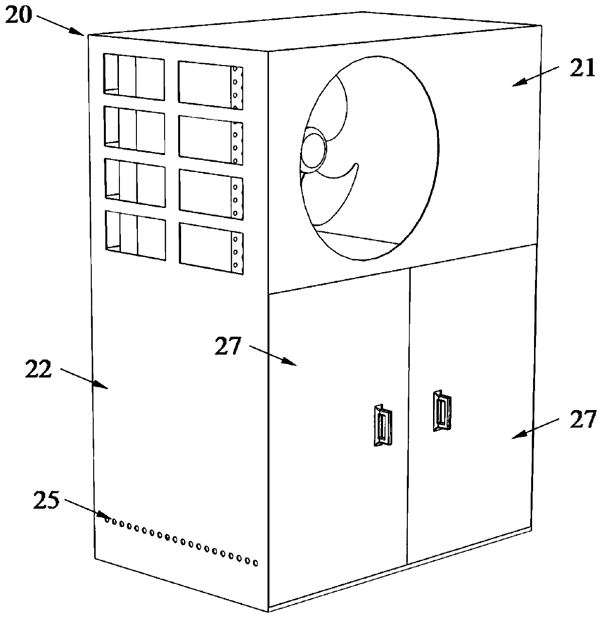
[0062] The wireless mobile air conditioner unit in this embodiment is composed of two parts: the movable air conditioner internal unit 0 and the regenerative charging external unit 20 . In the wireless mobile air-conditioning unit, the quantity of the above-mentioned movable air-conditioning internal unit 0 and regenerative charging external unit 20 is not limited, and an unlimited number of connection combinations can be performed.

[0063] The main structure of the mobile air conditioner internal unit 0 in this embodiment includes a casing, universal wheels 5, filter element protection shell, air return port 6, filter element 7, front door 8, dehumidification module 9, energy storage module 10, internal unit fan 11, battery 12. Charging port 13, display screen 14, air outlet 15, see figure 1 , figure 2 .

[0064] The shell of the movable air conditioner internal unit 0 is pasted with thermal insulation material on its inner wall. In the casing of the movable indoor air c...


PUM


Abstract

The invention relates to a wireless movable air conditioning unit comprising a movable air conditioning indoor unit and a regenerative charging outdoor unit. The movable air conditioning indoor unit comprises a first shall filter assembly, a dehumidification module, an energy storage module and a fan; the dehumidification module and the energy storage module are arranged in the first shell detachably; the regenerative charging outdoor unit comprises a second shell, and the second shell is internally provided with a regenerative charging refrigerant vapor compression circuit; the energy storagemodule can be connected with the interior of the regenerative charging refrigerant vapor compression circuit for heat / cold charging after being removed from the movable air conditioning indoor unit.Compared with the prior art, According to the wireless movable air conditioning unit, the indoor unit is provided with the dehumidification module and the energy storage module separately, and the energy storage module is used for cooling / heating air only; the regenerative charging outdoor unit has the functions of charging the energy storage module and regenerating the dehumidification module simultaneously, and the charging of the energy storage module and the regeneration of the dehumidification module can be performed simultaneously; and the use flexibility of the wireless movable air conditioning unit is improved.

Description

technical field [0001] The invention relates to a mobile air-conditioning system, in particular to a wireless mobile air-conditioning unit. Background technique [0002] The mobile air conditioner is a small air conditioner that is flexible and convenient to use. It is characterized by its small size. The refrigeration system and the air supply and exhaust system are compactly installed in a box. At the same time, the bottom is equipped with universal wheels, which can be moved and placed as needed (see CN203364278U). When in use, just plug in the power supply and connect the external air duct to realize the temperature and humidity adjustment of the indoor environment, which meets people's individual air-conditioning needs. [0003] However, in practical applications, the structural design of the traditional mobile air conditioner integrating the refrigeration system and the air supply device has the following disadvantages: 1. It is necessary to connect the power line and...

Claims


Application Information

Patent Timeline
Patent Type & Authority Applications(China)
IPC IPC(8): F24F5/00F24F3/14F24F13/32F24F13/28
CPCF24F3/14F24F5/001F24F5/0021F24F13/28F24F13/32F24F2003/1458F24F2221/125Y02E60/14
Inventor 成家豪德丽亚·克孜尔曹祥张春路
Owner TONGJI UNIV
Learn More