
Electric energy meter, electric energy meter calibration device, meter calibration station and electric energy meter calibration method

A technology of calibration devices and calibration methods, which is applied to measuring devices, measuring electrical variables, instruments, etc., can solve the problems of high production testing costs and low production efficiency, and achieve the effects of avoiding data interference and reducing communication wiring

Active Publication Date: 2020-08-21
CHIPSEA TECH SHENZHEN CO LTD
View PDF6 Cites 0 Cited by
  • Summary
  • Abstract
  • Description
  • Claims
  • Application Information

AI Technical Summary

Problems solved by technology

[0005] The main purpose of the embodiment of the present invention is to propose an electric energy meter, an electric energy meter calibration device, a meter calibration station and an electric energy meter calibration method, aiming at solving the problem that a large number of communication cables still need to be arranged during production and calibration of bluetooth electric energy meters in the prior art , leading to technical problems of high cost of production testing and low production efficiency

Method used


Image

  • Electric energy meter, electric energy meter calibration device, meter calibration station and electric energy meter calibration method
  • Electric energy meter, electric energy meter calibration device, meter calibration station and electric energy meter calibration method
  • Electric energy meter, electric energy meter calibration device, meter calibration station and electric energy meter calibration method

Examples


Embodiment Construction

[0032] It should be understood that the specific embodiments described here are only used to explain the present invention, not to limit the present invention.

[0033] In the following description, use of suffixes such as 'module', 'part' or 'unit' for denoting elements is only for facilitating description of the present invention and has no specific meaning by itself. Therefore, 'module', 'part' or 'unit' may be used in combination.

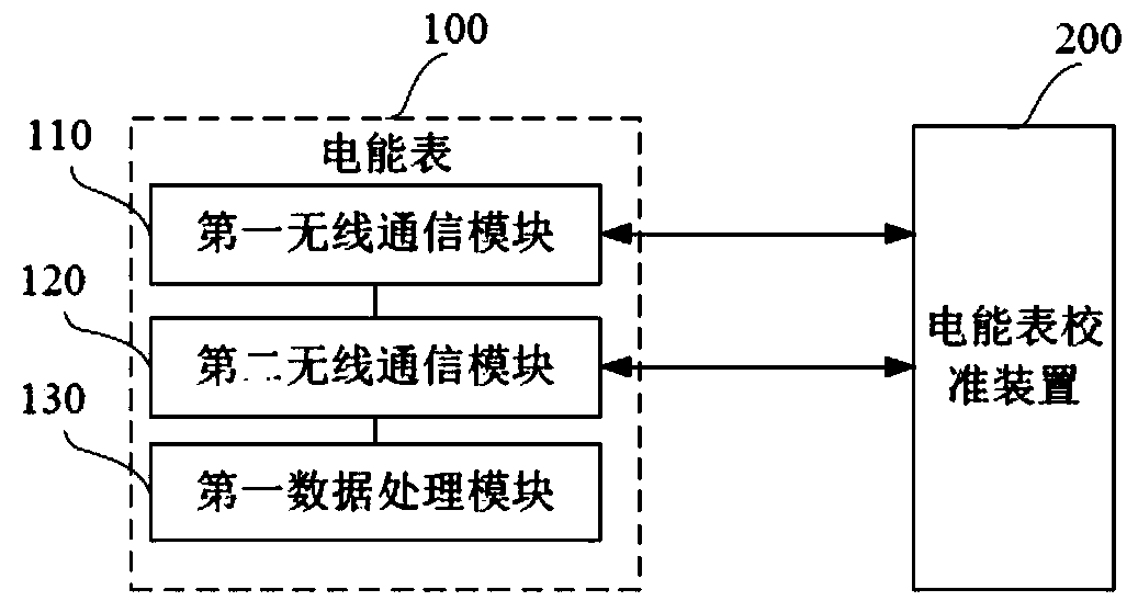
[0034] In one embodiment, such as figure 1 As shown, this embodiment proposes an electric energy meter 100, the electric energy meter 100 includes a first wireless communication module 110, a second wireless communication module 120 and a first data processing module 130, wherein the first data processing module 130 is mainly used for Convert preset calibration pulse signals into calibration data packets. During the calibration process of the electric energy meter 100 , two kinds of calibration pulse signals are required, which are metering p...


PUM


Abstract

The embodiment of the invention discloses an electric energy meter, an electric energy meter calibration device and an electric energy meter calibration method. The electric energy meter comprises a first wireless communication module, a second wireless communication module and a data processing module, the first data processing module is used for converting a preset calibration pulse signal intoa calibration data packet; the first wireless communication module is used for handshaking with the electric energy meter calibration device based on a preset standard protocol and configuring a preset transmission parameter between the electric energy meter and the electric energy meter calibration device; and the second wireless communication module is used for sending the calibration data packet to the electric energy meter calibration device at a first delay time based on a preset transmission parameter, so that the electric energy meter calibration device determines the to-be-calibrated parameter of the electric energy meter according to the calibration data packet, and the first delay time is less than the minimum delay time for data transmission based on a preset standard protocol.According to the technical scheme, real wireless meter calibration can be realized, one-to-one calibration of the electric energy meter and the electric energy meter calibration device can be realized, and the anti-interference performance is high.

Description

technical field [0001] The invention relates to the technical field of electric energy meter calibration, in particular to an electric energy meter, an electric energy meter calibration device, a meter calibration station and an electric energy meter calibration method. Background technique [0002] At present, electric energy meters on the market widely use wired RS485 interface to realize remote meter reading. Since the energy meter needs to send a calibration pulse to the meter calibration station for calibration of the energy meter before leaving the factory, a pulse interface for transmitting the calibration pulse signal is usually set on the energy meter. This method needs to arrange a large number of communication cables, the cost of production and testing is high, and the construction and production testing are troublesome. [0003] With the promotion of Bluetooth low-power technology, some Bluetooth energy meters have appeared on the market, but ordinary Bluetooth ...

Claims


Application Information

Patent Timeline
Patent Type & Authority Patents(China)
IPC IPC(8): G01R35/04
CPCG01R35/04
Inventor 陈定平
Owner CHIPSEA TECH SHENZHEN CO LTD
Learn More